Facebook
 Google
 GitHub
 Linkedin
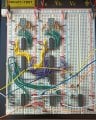
I have the counter working up to 1.7 MHz with a 74HC160 for the LSD, athough, digit #6 and digit #7Having just taken another look at the Carry Out signals of the two devices, I think you may need to put an inverter between the output of the last HC160 and the first CD4510, because the levels are the reverse of each other!
occasionally display a weird number briefly. The LSD always displays for example "2" then "3"
alternately or any other two consecutive numbers.
You were spot on with your suggestion about the inverter.
I did find that I need to pull the latch signal off of pin #7 of the monostable otherwise the LSD just
flashes wildly.
I guess I'll have to replace the "Tens" CD4510 with a 74HC160 as well. Hopefully that will
increase the range to 30 MHz and eliminate the weird digit #6 and #7 thing.