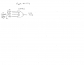
I came up with a technique for adding ripple blanking to CD4511s. It blanks the zeros but
when any number other than zero comes up, the displayed number flashes on and off. Any suggestions?
I came up with a technique for adding ripple blanking to CD4511s. It blanks the zeros but
when any number other than zero comes up, the displayed number flashes on and off. Any suggestions?
I think what may work is if the most significant digit is feeding into a 4 input OR as you show, but the following less significant ones each feed into a 5 input OR, with the output of the previous higher one being fed into the extra pin. That way a zero digit in the middle of a count will be overridden by the previous more significant digit.
This is all untested, just lying here in bed!
Edit: I could have sworn I'd seen 5 input OR gates in the past, but apparently not! So you'd have to feed the output of the 4 input into another OR gate and add the extra input into that new one!
Second edit: I just tried this out using CD4078 Single, 8 Input Nor/Or gates and it seems to work, although I didn't feed it into the CD4511's.
I had a problem in my case though because I used Motorola chips from 1976, and couldn't work out why I wasn't getting any output from the OR section. So I looked at the 4000 section on Wikipedia, and noticed that the original CD4078's didn't have the extra non-inverting output on pin 1 that current TI versions have. So I added inverters and solved the problem.
Probably best to use a CD4072 plus 2 gates from a CD4071 for every 2 CD4511's!
I've only had one coffee so far and my brain is still a little foggy. I guess my circuit for digit #7 (most significant digit) is okay.
I am not sure what you came up with for digit #6. Sorry. By the way I was using CD4071s and CD4072s but I didn't show that
on my schematic.
I've only had one coffee so far and my brain is still a little foggy. I guess my circuit for digit #7 (most significant digit) is okay.
I am not sure what you came up with for digit #6. Sorry. By the way I was using CD4071s and CD4072s but I didn't show that
on my schematic.
Your circuit is basically fine, except you are taking your blanking pulse from the wrong point. Mine is exactly as yours, with one difference.
It allows zero digits before the MSD to displays properly if anywhere in the series. I only tried it with LED's connected to the /BI outputs, and pulled various 4072 inputs up and down, and it seemed to work. Try it yourself!
Your circuit is basically fine, except you are taking your blanking pulse from the wrong point. Mine is exactly as yours, with one difference.
View attachment 337265
It allows zero digits before the MSD to displays properly if anywhere in the series. I only tried it with LED's connected to the /BI outputs, and pulled various 4072 inputs up and down, and it seemed to work. Try it yourself!
I tried the circuit just on the MSD. If the MSD is zero, then it is blank. If MSD is non-zero, the digit displays
but it flashes on and off. I can't help but wonder if it has something to do with the STORE and RESET
signals. I suppose if it flashed fast enough, it wouldn't even be noticeable. If only someone would have
come up with a chip that latched as well as handling ripple blanking.
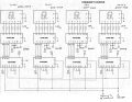
I have reduced the circuit to 4 digits for simplicity. Attached is the counter schematic and the ripple
blanking circuit. I have only dealt with digit #4 (MSD) initially. So far digit #4 gets blanked with a
zero but any other number displays and flashes on and off. If you require any more info please
advise.
I messed up with my circuit. I must have had the earlier 4042 idea still in my head, thinking that the /BI input was latched, sorry.
But I think if you added one d-type FF to each /BI line it could be made to work. I'm going to work through it for my own amusement if nothing else!
I messed up with my circuit. I must have had the earlier 4042 idea still in my head, thinking that the /BI input was latched, sorry.
But I think if you added one d-type FF to each /BI line it could be made to work. I'm going to work through it for my own amusement if nothing else!
I came to the conclusion that the only simple way to do it would be to put another set of latches between the counter outputs and the CD4511 inputs. But that kind of defeats the whole object really! Better to use a CD4033 (with LED drivers probably), or CD40110's (but no blanking again).
I came to the conclusion that the only simple way to do it would be to put another set of latches between the counter outputs and the CD4511 inputs. But that kind of defeats the whole object really! Better to use a CD4033 (with LED drivers probably), or CD40110's (but no blanking again).
Thanks for all of your advice and hard work. I really appreciate it. I find it difficult to understand why the chip designers
would come up with chips that don't have both ripple blanking and latches. It makes zero sense. The way I see it, a display
with leading zeroes is ridiculous.
Thanks for all of your advice and hard work. I really appreciate it. I find it difficult to understand why the chip designers
would come up with chips that don't have both ripple blanking and latches. It makes zero sense. The way I see it, a display
with leading zeroes is ridiculous.
There are only so many pins on a chip, and in those days 18 or 20 pin packages weren't as common, so something had to be left out, I suppose. It may have been better if they had left out 'Lamp Test' and subbed a proper 'Ripple Blanking Output' pin instead. You can always input '8' to test it!
I couldn't leave it alone, just had to see if it would work, and it does. I used the components that I had, and only built the first two stages.
To modify your circuit would need 2 74HC574 (or equivalent), 2 4072 and 1 4071 package.
The 74HC574, like the 40174 you were enquiring about, latches the input on the rising edge of the clock, so your monostable pulse can be quite short. The only problem with using the HC574 is its 5V limit, you can't use a higher voltage to get faster response from the CD chips to make a better counter! Its advantage is that all inputs are on one side, and the corresponding outputs are on the other.
The latch Enable input on the 4511's are permanently enabled, and the Latch pulse to the 74HC574's are commoned, as are the counter resets, of course.
This looks really interesting and it was a lot of work for which I am very grateful.
Dumb questions:
(1) Are you using the CD4518s in place of the CD4510s or in addition to the CD4510s?
(2) The "Input From Previous Stage" I am not sure about where it is connected.
This looks really interesting and it was a lot of work for which I am very grateful.
Dumb questions:
(1) Are you using the CD4518s in place of the CD4510s or in addition to the CD4510s?
(2) The "Input From Previous Stage" I am not sure about where it is connected.
I don't have any CD4510's, so substituted the CD4518, which has 2 Decade counters inside. As for the "Input From Previous Stage", that comes from the Q4 output of the next least significant stage down the line. I did wire a second CD4518 on the board, but found I hadn't got the room to add the extra HC574, 4072 and display to run the additional digits! My counters are wired in "Ripple Carry" mode, whereas yours are in "Synchronous" mode, the input signal sent to all counters together.
I think if I was to build such a counter I'd leave the least significant digit unblanked, so I'd get a zero there regardless!
 Facebook
 Google
 GitHub
 Linkedin