Facebook
 Google
 GitHub
 Linkedin
HiWithout seeing your circuit I can't say, but those chips won't be any faster at 10V than the CD4510's! Your best bet would be to replace the first one or two least significant CD4510's with CD74HC4510's, then you would be able to count at up to 30MHz minimum at 5V!
I built up a 4 stage version of your CD4510 counter after realising that the CD4029 counter is almost identical, except it doesn't have a Reset input, but has a Binary/Decade pin there instead. So by using the Preset Enable input as a Reset input, and setting it to Decade counting, it works exactly like the 4510!
The Overload circuit worked just fine, but I added the extra OR gate in line with the final Carry Out, and OR'red it with the Input Clock signal, as per the datasheet suggestion about spurious glitch pulses, noted in figure 13 in the CD4029 sheet, and the CD4510 one!
I did notice that you used pin 7 (/Q) as the Latch signal to the 574's. This means that they don't latch the count value until about 1us after the true timeout of the timebase. This won't matter for slow inputs, but will add counts if you make measurements above 1MHz. It also means that it is latching at the same time as the Reset pulse is happening! I'd move it back to the Q output.
The 74HC4510 sounds ideal. I can't find anyone that sells them.
I should clarify that I was trying out the CD40174BEs initially because they can be used with a supply
of up to 20 volts. But then I thought I would use 1 for each digit (only using 4 of 6 latches) rather
than using the 74HC574s (where I used only 1 for every 2 digits). It would make the wiring a lot
neater especially when I build this thing on perfboard. The thing is, the CD40174BEs don't seem to
work at all. I also used CD4072BEs in place of the CD4071BEs in an attempt to reduce component
layout issues later. See attached.
I realize now why I thought that the overload wasn't working. My 7-digit counter only works up to
about 1.2 Mhz. The LED won't come on until the MSB counter "carry out" tells it to. That can't happen
because the count will never get that high.
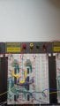
Attachments
-
30.4 KB Views: 3
Last edited: