It might be the overflow in the readings.
Maybe you can just skip the values where x and y both
are 00 00 = 0 or 255 255 = - 1 after converting from twos complement?
It might be the overflow in the readings.
Maybe you can just skip the values where x and y both
are 00 00 = 0 or 255 255 = - 1 after converting from twos complement?
With 16bit the 7'h number ST2 should be 16 decimal when no overflow, 20 when overflow.
It should never be 255 or 0.
Maybe you are reading from wrong addresses or there is some hw problem?
With 16bit the 7'h number ST2 should be 16 decimal when no overflow, 20 when overflow.
It should never be 255 or 0.
Maybe you are reading from wrong addresses or there is some hw problem?
Hi J,
Remember I change one of the other bits to '0' and got the correct READing, so I'm pretty sure I'm READing correctly.
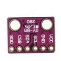
So this points to, as you say, hardware. I'm about to remake some PCBs, what should I change?
C.
I might got this wrong.
+-32767 corresponds to 4192uT field strength, but Earth's field strength is only about 30-60uT.
Why is then 16bits used for the results?
Hi J,
Connected copper to GND, slight improvement.
It still failed when I touched it. I notice it was more sensitive when one area was touched, then narrowed it down to the RSTN PIN, which is now connected to VID.
I think we've found it It's been stable for an hour, while touching.
Hi,
Here's a progress update:
Previously, I used a PCB with an 18LF4520 PIC for testing each of the modules. 5110 Nokia screen, BMP280 as Altimeter, AK8963C Compass, HC-12 Radio.
Both TX and RX are the same, with variations e,g, SERVOs on the RX (Mainly the program)
Due to low memory of the 18LF4520, and the conflict timings for the RX SERVOS, I now have a PCB with two PICs. 18F4620 and 18LF2520.
I now have all of the modules connected to the PCB. I read the outputs of the modules, via an HC-12 on the PCB and another connected via a serial USB to a computer screen.
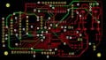
All of the modules are attached along with a circuit SCH and PCB.
Using the latest program:
I the Compass and altimeter and radios are working. I'm working on the GPS section now.
Morning E,
Not yet.
The GPS compiles, but doesn't work LIVE. I've got to check the DATASWITCH and see what's happening.
Still got to get the 5110 screen working.
C.
I think you are now reading the compass values in wrong order.
It was correct, when you tested with Magmaster program.
Correct order : X. LB, X. HB, Y. LB., Y. HB, Z. LB, Z. HB
Hi J,
I've copied and pasted the Magmaster Compass values into the program.
Are they in the correct order now?
IMAGES:
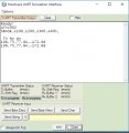
SIM: Shows the results when $BASE,1100,1200,1300,1400,? is entered into the SIM SEND STRING.
FAST: Shows the result from the PCB received in the computer TERMINAL when PIC is running with the SIMULATION_WAITMS_VALUE = 1.
LIVE TX RX: RXERR! from the PCB plus $BASE,1100,1200,1300,1400,? sent from a second TX TERMINAL. I assume then that the PIC is not READing the GPS input, as the TERMINAL should show both IN and OUT of the PCB. Previously, the Compass and ALT were shown.
Hi,
I've made a few changes to the program, including to the 5110 screen section. I may have stepped forward a little while also stepping back a bit
Anyway, I am now getting tentative GPS results, but there maybe issues with the RX INPUT switch.
The TIME/LOCATION calculation works when NMEA sentences are sent from a 2nd computer TERMINAL/SERIAL OUTPUT, but so far not from a GPS module INPUT.
The program only 'sees' $GPRMC sentences, but is set for $GPGGA. See below.
C.
EXAMPLES:
'''''''''''''''''''''''''''''''''''''''''''''''''''''''''''''''''''''''''''''''''''''''''''''''''''''''''''''''''''''''''''''''''''''''''''''''''''''''''''''''''''''''''''''''''''''''''''''''''''''''''''''
$GPRMC,123519,A,4807.038,N,01131.000,E,022.4,084.4,230394,003.1,W*6A
Recommended Minimum sentence C
123519 Fix taken at 12:35:19 UTC
A Status A=active or V=Void.
4807.038,N Latitude 48 deg 07.038' N
01131.000,E Longitude 11 deg 31.000' E
022.4 Speed over the ground in knots
084.4 Track angle in degrees True
230394 Date - 23rd of March 1994
003.1,W Magnetic Variation
*6A The checksum data, always begins with *
''''''''''''''''''''''''''''''''''''''''''''''''''''''''''''''''''''''''''''''''''''''''''''''''''''''''''''''''''''''''''''''''''''''''''''''''''''''''''''''''''''''''''''''''''''''''''''
$GPGGA,123519,4807.038,N,01131.000,E,1,08,0.9,545.4,M,46.9,M,,*47
GGA Global Positioning System Fix Data
123519 Fix taken at 12:35:19 UTC
4807.038,N Latitude 48 deg 07.038' N
01131.000,E Longitude 11 deg 31.000' E
1 Fix quality: 0 = invalid
1 = GPS fix (SPS)
2 = DGPS fix
3 = PPS fix
4 = Real Time Kinematic
5 = Float RTK
6 = estimated (dead reckoning) (2.3 feature)
7 = Manual input mode
8 = Simulation mode
08 Number of satellites being tracked
0.9 Horizontal dilution of position
545.4,M Altitude, Meters, above mean sea level
46.9,M Height of geoid (mean sea level) above WGS84
ellipsoid
(empty field) time in seconds since last DGPS update
(empty field) DGPS station ID number
*47 the checksum data, always begins with *
'''''''''''''''''''''''''''''''''''''''''''''''''''''''''''''''''''''''''''''''''''''''''''''''''''''''''''''''''''''''''''''''''''''''''''''''''''''''''''''''''''''''''''''''''''''''''
Hi E,
To clarify: This is the REMOTE RECEIVER. It will collect the GPS LOCATION from it's on-board module, also 6X SERVO INPUTs, which will be the basis of the LOCATION CONTROL.
Here's the parse section:
Can the 'dataswitch' = 1 '0=HC-12 1=GPS, be incorporated so the INPUT SWITCH is correctly positioned.
At the time the GPS image was captured, the GPS was showing full GGA and RMC sentences.
NOTE: I've commented out all TMR CODE from the program??
hi C,
You appear to be using the same get_val subr for both messages,by finding the csv value.
The two message strings are different in their construction.
Two different get_val subr and csv subr are required,
E
hi C,
You appear to be using the same get_val subr for both messages,by finding the csv value.
The two message strings are different in their construction.
Two different get_val subr and csv subr are required,
E
Hi E,
Note: I've been testing the 'dataswitch' and it looks as though, when switched one way, the two DATA INPUTs are merging at times. Still testing.
Yes, the second message is commented out, while I/we get the first one working, then I'll add the second. I'm using NMEA $ sentences for both inputs for testing, one from the GPS and the second via a serial INPUT, so both should PARSE but give different results.
 Facebook
 Google
 GitHub
 Linkedin

") It's been stable for an hour, while touching.
It's been stable for an hour, while touching.