Facebook
 Google
 GitHub
 Linkedin
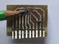
Hi J,I bought the AK8963 already on a breakout board. Yes, it is more expensive, but it was working the day I received it too. If I were in production, of course I would buy the bare chip.
Do you have a link for the AK8963 breakout board, please?
C.


")