Remote control by location (PIC in Oshonsoft)

Thread Starter

camerart

Joined Feb 25, 2013
3,835
Hi,
A quick update:
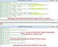
I've just kind of wasted a few weeks simulating the programs, to make sure they were discriminating good sentences from bad ones at the beginning of the sentence e,g, GNRMC=GNRMC.
I simulated every odd sentence as bad, which appeared to be working, but I've just found out that the SIM was missing every second sentence, which looked as I thought it was disciminating :(
C.
 
Last edited:

Thread Starter

camerart

Joined Feb 25, 2013
3,835
Hi,
I'm hoping that all messages between BASE and REMOTE and GPS are ok, so I'm leaving out the message 'good sentence discrimination' section till later.

I think all is working on the BASE PIC pair, so some tidying up, then copy most of it to the REMOTE PIC pair, with the obvious? differences, and hope they start talking to each other.

Thank you all for getting me this far :)
C
 

Attachments

Thread Starter

camerart

Joined Feb 25, 2013
3,835
Hi,
At last BASE and REMOTE are 'talking' to each other! There are a lot of glitches in it, and it needs coaxing to keep it running.

The REMOTE's output, which would be stuff like battery voltage, isn't wired up, to it sends a dummy message, so the system works.

Here's an image: The top view is a terminal connected to a PIN on the PCB, for monitoring.
The Bottom is the messages between them, so the long line would have CONTROL DATA in it.

There are a lot of glitches in it, and it needs coaxing to keep it running.

EDIT: I've just noticed the 2xPRESSURE from each unit are results are very different, the SLAVE is wrong. It was ok earlier.
There is only 1x bit of DATA correct so far and that's the '1' in TOFRO.
C.
 

Attachments

Thread Starter

camerart

Joined Feb 25, 2013
3,835
Hi,
Up to now, approx 6 years, this project has been dealing with 4 PIC programs, on 2x PCBs BASE and REMOTE, getting all of the sensor peripherals to 'talk' to each other and send messages beteen BASE and REMOTE. I think we are just about there.
If there are any questions regarding CODE for the above, please post it here. The CODE now needs proof reading and I'm sure there will be lots of modifications to the CODES. Once they look about right I'll post them here.

I'm going to start another thread for the actual control, between these modules, which is the whole idea for the project, and a completly different thing, that I'm looking forward to.
Thanks for all of the help :)
C.
 

Thread Starter

camerart

Joined Feb 25, 2013
3,835
Hi,
Sometime back I made a comment that the BASE and REMOTE are communicating with each other, so when the joysticks on the BASE unit are moved, then the SERVOs on the REMOTE move, but some of the PICs keep stalling occassionally, and I haven't been able to figure out what the problem/s are.

During the 5ish years of the project, I've spent may hours, and many of you have also, but I've got to lessen my efforts on it, so I wonder if it will ever get finished.

If anyone wants to take it on, with my help, I can send all of the information.

Cheers, C.
 

Thread Starter

camerart

Joined Feb 25, 2013
3,835
Hi,
There appears to be a problem with the PCBs!
I am trying to figure out what's wrong, but it must be more on the advanced side of electronics, so above my skills, so far.
C
 

Thread Starter

camerart

Joined Feb 25, 2013
3,835
Why you think it is PCB problem, not software?
Hi T,
I've been using this PIC for years, and had odd problems, and 2x forums have tried and failed to get to the bottom of.
Yesterday I swapped the PIC on one of my 3x boards, and it now works, so some work and some don't. I sent a 4th board to a forum member, who also tested it and the only common denominator is the PIC. There is another on the forum, who is using a TTH 18F46K20, with no problems, and 2x others with a slightly different PIC with no problems.
C
 

Thread Starter

camerart

Joined Feb 25, 2013
3,835
Hi,
It's been suggested that the power supply could be a problem!

The PIC is normally powered by a 12V battery, though a 7805, then through a 3.3V LDO.
I tried a 5V battery before the LDO and a 3V cell after the LDO, and the PIC works powered by 3V after the LDO, and sometimes can be jumped to work 5V before the LDO.
There are capacitors, all around!
The crystal always works, but in this case, not working means a TFT screen using SPI.
It doesn't work when the 3.3V comes from my rework station.

So my PCB is affecting the 18F46K20! and in this case the weakest link is the 3.3V LDO
This problem is so intermittent, that it's difficult to figure out exactly how to proceed.
C
 
Last edited:

trebla

Joined Jun 29, 2019
599
Can you explain more please? What is 'stalling' and how do you think the PIC is damaged?
Because you wrote in post #1306:
some of the PICs keep stalling occassionally
and in post #1312 you wrote:
Yesterday I swapped the PIC on one of my 3x boards, and it now works
There may be some reasons related with two different voltage regulators so try to find out how to power both PIC MCUs from one supply. Two PIC MCUs are connected with each other directly and via these I/O pin protection diodes can also flow supply current if there is enough difference in supply voltage.
There maybe is some silicon issues as i read from the PIC18F46K20 errata sheet - one is connected with SPI master mode and another is related to Power On Reset module. Some of these issues have work-arounds in software but some not. The PIC18F46K22 errata sheet looks much better. Unfortunately i don't know the software you have implemented so maybe some other in this forum can check out if there is any silicon issues connected to your software.

The PIC18F4620 does'nt look any better and at 3.3V it works not always reliable with 20MHz oscillator.
 

Thread Starter

camerart

Joined Feb 25, 2013
3,835
Because you wrote in post #1306:

and in post #1312 you wrote:


There may be some reasons related with two different voltage regulators so try to find out how to power both PIC MCUs from one supply. Two PIC MCUs are connected with each other directly and via these I/O pin protection diodes can also flow supply current if there is enough difference in supply voltage.
There maybe is some silicon issues as i read from the PIC18F46K20 errata sheet - one is connected with SPI master mode and another is related to Power On Reset module. Some of these issues have work-arounds in software but some not. The PIC18F46K22 errata sheet looks much better. Unfortunately i don't know the software you have implemented so maybe some other in this forum can check out if there is any silicon issues connected to your software.

The PIC18F4620 does'nt look any better and at 3.3V it works not always reliable with 20MHz oscillator.
Hi T,
I've been looking at the ERRATA D/Ss and notice with 18F46K20, many are related to SPI.
The previous project using these boards, had 5 or 6 peripherals, all using SPI, and set to a particular SPI MODE. I haven't found yet a definitive setting for these ST7789 TFT screens yet, but suspect they are slightly different than my settings perhaps the CKL REST setting?
C.
 

Thread Starter

camerart

Joined Feb 25, 2013
3,835
Hi,
I've had a long break 'holiday' and may have another look at this, since getting better results with SPI with an 18LF46K22 pic.
I've also bought a proper drone, which is completely different to how I imagined it to be.
C.
 
Top