Remote control by location (PIC in Oshonsoft)

Thread Starter

camerart

Joined Feb 25, 2013
3,724
I'm making a couple of PCBs BASE/TRANSMITTER and REMOTE/MODEL RECEIVER using surface mount components, and PICs, for use as remote control by location (3D).

Remote control by location, is when a location is sent from the BASE (Transmitter) and the REMOTE (Model) goes to that location. This includes GPS COORDINATES, ALTITUDE and COMPASS BEARING,.SENSORS.

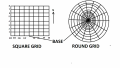
For the first tests, 'the field' will be thought of as a SQUARE GRID, see attached. (The CIRCLE GRID may be for the future)

START UP: The REMOTE is at the BASE LOCATION, HEIGHT aiming NORTH. All location settings are ZEROed, so now both BASE and REMOTE are set to ZERO.

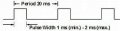
The easiest component of the location dimensions to explain is ALTITUDE. Normally for a model to gain ALTITUDE is to move the THROTTLE forward and the motor/s speed up. In this case the THROTTLE will add ALTITUDE to the previous setting, 'say' ALTITUDE + 1 (+1 if THROTTLE held forward) could be 1Mtr above ground, so the motor/s will speed up till 1MTr is achieved, then control a 1MTR ALTITUDE till another setting is sent, and so on. In a similar way the other DIMENSIONS (3D) can be set, by this method.

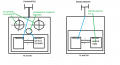
The BASE PCB (18F46K20) will be built into a radio control TRANSMITTER, the REMOTE RECEIVER (18F46K20 + 18LF2520) will be built into the MODEL. The BASE will use the STICKS pots/SWITCHES outputs to calculate a set of numbers to transmit to the REMOTE, which will use them, combined with it's own SENSORS to calculate PWMs which it will pass to the 182520 PIC on it's PCB, to control the SERVOS/MOTORS.

Camerart.
 

Attachments

Last edited:

Thread Starter

camerart

Joined Feb 25, 2013
3,724
I received a reply in another thread and I've moved it here:

TRIBBLES "I never really got to play with the PWM on PICs, so I'm going on intuition here....

HPOL and LPOL are the high and low polarity - i.e. whether the signal needs to be high or low to turn on a transistor/MOSFET. Figure 18-2 shows that it's used to select the normal or inverted output of the PWM block.

PWMPIN I think needs to be '1' to indicate that you want the pin to use the PWM block. Figure 18-23 shows that "PWM Pin Enable" switches between the LAT output for the pin, and the output from the PWM block. It looks like the PWM Pin Enable signal also overrides the TRIS configuration as well.

And I've just read 18.11.3 which confirms my understanding of the PWM Pin Enable signal.

Now looking into it a bit more, the PWMPIN configuration bit drives the default setting for the PWMEN register - so if you're manually setting PWMEN in your code (which you are - the 0x40 value in PWMCON0), then it doesn't matter what you set the PWMPIN configuration bit :) The only two values that it'll default to is 0x50 or 0x70 - so you can't configure it to 0x40 by this bit, and you'll have to override it anyway."

HI T,
I'll check out your findings, thanks.
C.
 

Thread Starter

camerart

Joined Feb 25, 2013
3,724
Hi
Setting up PIC 18LF4431 PWM PINs is quite involved. I'm trying to get 6x PWM outputs, like this:

Also there may be a problem regarding actually writing the program, as last time I was playing with PWMs, EG wrote this program for me, using ASM, because I can't. Trying this program in the Oshonsoft SIM, it looks as though it may be possible to run it with just one PIN. I'll need to check a bit more.
EDIT: I don't think the attached program lends itself to the 18LF4431 PIC.
C.
 

Attachments

Last edited:

Thread Starter

camerart

Joined Feb 25, 2013
3,724
Hi,
I've been reminded again, by a web search that PWM in Oshonsoft needs this:

" Hi C,
If you recall there is a bug on Oshonsoft PWM, it does not clear the CCPRxL reg correctly, it was reported to Vlad.
You and I have used this ASM in dozens of programs already, I don't see a problem with using it again.??

E

hcw: ' clock wise
Hserin dutyhcw 'duty 0 thru FFh
ASM: bcf CCP1CON,DC1B0
ASM: bcf ccp1con,dc1b1
ASM: movlw 0x00
ASM: movwf ccpr1l
PWMduty 2, dutyhcw
Goto main

hacw: ' anti clock wise
Hserin dutyhacw 'duty 0 thru FFh
ASM: bcf CCP2CON,DC2B0
ASM: bcf ccp2con,dc2b1
ASM: movlw 0x00
ASM: movwf ccpr2l
PWMduty 1, dutyhacw
Goto main "

So, I'll have to try it again.
 

ericgibbs

Joined Jan 29, 2010
18,766
hi C,
I am not sure I follow your question.?
Hserin gets the 'pwm duty'
the ASM sets up the correct CCP2CON
PWMduty is the Oshonsoft output command to the PWM pin
e
 

Thread Starter

camerart

Joined Feb 25, 2013
3,724
Hi E,
If you look at the '20ms PERIOD PWM' in #3

I need to have 6x PWM output PINS in an approx 1second LOOP.

I'm not at all sure how this can be done, remembering that SERVOs jitter if not run correctly. I noticed from looking back into threads, where I asked about whether I may need a dedicated PIC just to run 6xSERVOs

C
 
Last edited:

Thread Starter

camerart

Joined Feb 25, 2013
3,724
Hi,
Just looking at page 149 of the D/S, 16.5 PWM Mode.

Initially this looked promising, but it appears to output at the CCP1 and not the expected 6x PWM PINS, which are outputs on my PCB:confused:

C.
 

ericgibbs

Joined Jan 29, 2010
18,766
hi C,
I doubt if Oshonsoft Basic can cover 6 PWM pins.????
It should be possible to use a ASM program block, in Oshonsoft Basic, using a suitable PIC that has 6 PWM's
E
 

ericgibbs

Joined Jan 29, 2010
18,766
hi C,
Looking at the 18F4431 d/s suggets that 6 PWM pins are possible.
Write a simple program for say just 3 PWM's and see if that is OK.
E
 

Thread Starter

camerart

Joined Feb 25, 2013
3,724
hi C,
Looking at the 18F4431 d/s suggets that 6 PWM pins are possible.
Write a simple program for say just 3 PWM's and see if that is OK.
E
Hi E,
Ok, do I use the CODE in #4?

EDIT: I don't understand ASM as in #4, but if I recall correctly, this uses two PINs for each PWM output, and can drive an H-Bridge. I need the type of PWM that only uses one PIN, and will drive a SERVO, which has it's own H-Bridge in it's circuit. E suggests using a dedicated PIC for only PWM.

C.
 
Last edited:

Thread Starter

camerart

Joined Feb 25, 2013
3,724
Hi,

I've searched around and found some CODE which maybe what's needed for running multiple SERVO PWM PINS from a PIC.

It's written in 'C' which I have difficulty understanding, but kind of follow. I've copied it into an Oshonsoft program and tried to change it to BASIC. Here's where I've got to so far. Does it look promising?

I notice that LAT is used, instead of PORT, so perhaps I'll be able to 'get it' once I've used it.

C.
 

Attachments

Thread Starter

camerart

Joined Feb 25, 2013
3,724
Hi,
I'm kind of starting again, using information learnt since I started this post.

Both TRANSMITTER PCB and RECEIVER PCB with use 18LF4520

Here is a starter program which will READ a message, e,g, It is set for NMEA sentence at the moment, but can be used for messages between the UNITS (TX UNIT RX UNIT) Will someone run it in OSH SIM please and check it, then if ok, I'll split it into two programs TX and RX. (There is a copy and paste sentence 'get_mess: ' for HARDWARE UART)

The TX will then be fitted into a Radio control transmitter (original radio electronics removed) set to READ 6 inputs ANALOG or DIGITAL. after a calculation the result will be SENT to the RECEIVER via a HC-12 radio module.

The RX, will RECEIVE the TRANSMITTER MESSAGE via a HC-12 radio module and convert the MESSAGE to 6x SERVO/MOTOR CONTROL outputs attached to a model.

Later GPS,COMPASS, ALTIMETER/BAROMETER will be added to both PCBs, for location.

C.
 

Attachments

Last edited:

ericgibbs

Joined Jan 29, 2010
18,766
hi C,
This is the same working program I posted for you a while ago, using the SPI 5110 graphics LCD.??
Are you having a problem with it.?
E
 

Thread Starter

camerart

Joined Feb 25, 2013
3,724
hi C,
This is the same working program I posted for you a while ago, using the SPI 5110 graphics LCD.??
Are you having a problem with it.?
E
Hi E,
No problems, There are some small changes, but nothing major. I wanted to make sure it was ok, before moving on. I'll now make two from one.
Thanks, C.
 
Last edited:

ericgibbs

Joined Jan 29, 2010
18,766
hi C,
You cannot use the same label for two assignments, try this.

E
'#####################################################
Dim vpot0 As Byte
Dim vpot1 As Byte
Dim vpot2 As Byte
Dim vpot3 As Byte
Dim vpot4 As Byte
Dim vpot5 As Byte
ADCIN 0, vpot(0)
ADCIN 1, vpot(1)
ADCIN 2, vpot(2)
ADCIN 3, vpot(3)
ADCIN 4, vpot(4)
ADCIN 5, vpot(5)
 
Last edited:

Thread Starter

camerart

Joined Feb 25, 2013
3,724
hi C,
You cannot use the same label for two assignments, try this.

E
'#####################################################
Dim vpot0 As Byte
Dim vpot1 As Byte
Dim vpot2 As Byte
Dim vpot3 As Byte
Dim vpot4 As Byte
Dim vpot5 As Byte

vpot0 = adc_read(0)
vpot1 = adc_read(1)
vpot2 = adc_read(2)
vpot3 = adc_read(3)
vpot4 = adc_read(4)
vpot5 = adc_read(5)
Hi E,
See attached:
C.
 

Attachments

ericgibbs

Joined Jan 29, 2010
18,766
hi C,
I had removed your Symbols, so use the Oshonsoft code designations.
I would suggest you don't use symbols, use the actual Oshonsoft ID's, once the program is working you can then tidy it.
Also you did not post your Fonts Include, so I could not run it.
E
Dim vpot0 As Byte
Dim vpot1 As Byte
Dim vpot2 As Byte
Dim vpot3 As Byte
Dim vpot4 As Byte
Dim vpot5 As Byte
ADCIN 0, vpot(0)
ADCIN 1, vpot(1)
ADCIN 2, vpot(2)
ADCIN 3, vpot(3)
ADCIN 4, vpot(4)
ADCIN 5, vpot(5)
 
Top