Facebook
 Google
 GitHub
 Linkedin
Hi E,hi,
The get_mess is extinct.
Copy and over Paste that Low Int with this code clip.
Rerun the test
E
BTW: for this test I have disabled timer1 int, re-enable ans see the print out
EDIT:
Added the hser print
View attachment 157414
")
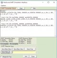
The STR1 STRING isn't clearing, so it seems it's corrupting the next sentence.
TMR1 enabled.
C.
Attachments
-
 105.8 KB Views: 4