Hi there. Help me understand this relaxation oscillator. What happens at the input. What are the trip points? The charging and discharging times. Thanks, Etonam.
Hi. This is not homework. I'm not student. This is personal endeavour. My previous thread was about my hot air temp control. While going thru some litterature, I saw this oscillator. But the author didn't give a detailed explanation. This oscillator is close enough to the 2nd stage in my hot air. So if I can grasp this one, I'm pretty sure I can understand in detail the hot air 2nd stage. So to not waste more time in trying alone, I'm putting to you, more knowledgeable out here. This RC oscillator certainly is taught in schools. But never needed to know about it til now. Would be nice also if u could recommend me a book/paper that explains such in detail. Thanks for ur time, Etonam.
Don't build that circuit, it's a circuit to destroy your comparator's inputs. Build the one in @ericgibbs video instead.
Also, not that this is not an amplifier, and there is no guarantee it will work with an op-amp. It needs a comparator.
Imagine the circuit starts with the output at the negative supply. R1 and R2 set the threshold to half the supply (assuming that they are equal values). The capacitor starts to charge through R and when it reaches -7.5V the output swaps state. Not that the voltage at that point is 7.5V above the output. It follows that AFTER it changes state the capacitor voltage is STILL 7.5V above the output. That's 22.5V, and those inputs are not going to like that.
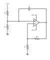
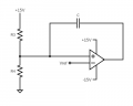
Hello again. ericgibbs I already watched the video you referred to. But here in circuit.png, the feedback paths swap input. The voltage divider is now on the - input while the RC branch in on the + input with C in the feedback and R from + to gnd. Thks for your reply Ian0. You think this circuit I'm investigating is impractical and should be tried rather w/ a comparator. fine. But it was featured on this paper: https://epub.jku.at/download/pdf/9162356.pdf , on pg 7, fig. 9 and on fig. 10 you have the waveforms. The author didn't go in detail on the equation for the trip point, for me to clearly see how C toggles from charging to discharging. From what u said, Ian0, it is the voltage divider on - input that sets the trip point. If that's correct, thk you. So if I get u right, trip point TP= ±[R1/(R1+R2)]Vsat. And TP is on the - input. Right? Allow me to remind you the reason I'm trying to understand this variant RC oscillator. In my previous thread (https://forum.allaboutcircuits.com/threads/hot-air-temp-control-circuit.207962/), which is a hot air temp control circuit, stage 2 around U1.2 is an RC oscillator close in structure to the one, topic here in this thread. And making it simple, I think U1.2 looks more like this (circuit2.png), except for the - input which comes from U1.1 output and the missing resistor in series w/ C. Coming back to this thread, I understand circuit.png, I can understand circuit2.png and then grasp my hot air circuitry, and get the necessary equations in place : charging/discharging time, frequency. OK. To recap, TP= ±[R1/(R1+R2)]Vsat in circuit.png, right? So, here TP, unlike the typical relaxation osc. is set on the - input, not the + input. ok. So from this point, assuming everything is correct, I should be able to figure out charging/discharging time and freq for circuit.png Please confirm if I am correct. Thanks for ur time, Etonam.
Hello again. ericgibbs I already watched the video you referred to. But here in circuit.png, the feedback paths swap input. The voltage divider is now on the - input while the RC branch in on the + input with C in the feedback and R from + to gnd. Thks for your reply Ian0. You think this circuit I'm investigating is impractical and should be tried rather w/ a comparator. fine. But it was featured on this paper: https://epub.jku.at/download/pdf/9162356.pdf , on pg 7, fig. 9 and on fig. 10 you have the waveforms. The author didn't go in detail on the equation for the trip point, for me to clearly see how C toggles from charging to discharging. From what u said, Ian0, it is the voltage divider on - input that sets the trip point. If that's correct, thk you. So if I get u right, trip point TP= ±[R1/(R1+R2)]Vsat. And TP is on the - input. Right? Allow me to remind you the reason I'm trying to understand this variant RC oscillator. In my previous thread (https://forum.allaboutcircuits.com/threads/hot-air-temp-control-circuit.207962/), which is a hot air temp control circuit, stage 2 around U1.2 is an RC oscillator close in structure to the one, topic here in this thread. And making it simple, I think U1.2 looks more like this (circuit2.png), except for the - input which comes from U1.1 output and the missing resistor in series w/ C. Coming back to this thread, I understand circuit.png, I can understand circuit2.png and then grasp my hot air circuitry, and get the necessary equations in place : charging/discharging time, frequency. OK. To recap, TP= ±[R1/(R1+R2)]Vsat in circuit.png, right? So, here TP, unlike the typical relaxation osc. is set on the - input, not the + input. ok. So from this point, assuming everything is correct, I should be able to figure out charging/discharging time and freq for circuit.png Please confirm if I am correct. Thanks for ur time, Etonam.
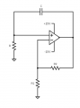
Why did you add another resistor to the first circuit you had shown?
This is an unusual oscillator circuit. For one, for some values for the resistances the exponential may actually be an increasing exponential that rises up faster and faster as time goes on. That's very different than the usual oscillator circuit. So you do need to show the resistor values so we can calculate the exponentials involved. That will reveal the switching times.
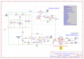
Sorry. I didn't mean to confuse. My aim in using these 'simple' circuits is to understand this (LongTech_HotAir.png), especially the oscillator around U1.2 w/ exactly the values there. Please take a look, and tell me from ur calculations if this can work. And if u wish, I can draw a separate diagram for the oscillator w/ the values given. Thank u.
Below is the LTspice sim of your Post #9 circuit with typical circuit values showing the node voltages and capacitor current:
Positive current through C1 is right to left.
Sorry. I didn't mean to confuse. My aim in using these 'simple' circuits is to understand this (LongTech_HotAir.png), especially the oscillator around U1.2 w/ exactly the values there. Please take a look, and tell me from ur calculations if this can work. And if u wish, I can draw a separate diagram for the oscillator w/ the values given. Thank u.
That's not an oscillator at all, it's just a comparator with some Ac-coupled hysteresis. Note the absence of a resistor in the position equivalent to R2 in your original diagram. It's just a classic example of using an op-amp where you really should have used a comparator, finding that the op-amp doesn't work very well in that application because it is too slow, then trying to make amends by giving it a bit of positive feedback.
Almost, it's got a high-value resistor in series with capacitor to prevent it taking the input voltage outside the supply rails.
If you draw it WITH the resistor and WITHOUT the capacitor you can see it just a comparator with small amount of hysteresis.
The Capacitor puts a time limit on the hysteresis.
But don't believe that simulation! The LMC6484 has a maximum supply voltage of 16V, and @crutschow is running it on 30V. Also TI's datasheet says: "The absolute maximum input voltage is 300mV beyond either supply rail at room temperature. Voltages greatly
exceeding this absolute maximum rating, as in Figure 6-3, can cause excessive current to flow in or out of the
input pins possibly affecting reliability.
Applications that exceed this rating must externally limit the maximum input current to ±5mA with an input
resistor (Ri) as shown in Figure 6-4."
That means that it has clamp diodes to the supply rails,[EDIT] and you can see the current spikes that result, which will make a mess of the timing calculations.
Alright. So far, I'm grateful for the insight you all provided me. I see amends have to be made to this circuitry. First choosing a proper comparator ic like LM339? Allow me to shift the focus on LongTech_HotAir.png (post #12) U1.1 is a non-inverting amplifier that amplifies the voltage on the thermocouple sensor and feeds the output to the - input of U1.2 From ur observations, I should add a resistor network in negative fdbk to the output of U1.2 The goal of this circuitry is to get at U1.2 output, a square wave which duty cycle can be varied from the 10-k pot at the input, to control the hot air temp. And the thermocouple sensor, I guess help set the reference as to protect the hot air.
I know it's a bit of a bodge, but it is probably going to work. A comparator but with a push-pull output would be better.
What is meant to happen with the blower control? It seems to bias the MOSFET into a linear mode, where it might overheat, depending on the size of the blower motor.
 Facebook
 Google
 GitHub
 Linkedin
 6.3 KB Views: 34