 Facebook
 Google
 GitHub
 Linkedin
Hi guys, I need an insight, please help me.
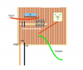
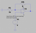
I'm building a non-inverting amplifier, where the goal is to amplify a 32 MHz low-passed-input signal. 1kΩ fixed resistor, and a variable resistor with max of 10kΩ.
The original signal is a 100 ps pulse at 500 kHz, connected to a photodiode (PDA10A2). This is then passed through a commercially available 32 MHz low-pass filter (Mini-Circuits – 32 MHz, 50 Ω | SLP-30+), which filters out high frequencies. The output from this filter is connected via a probe to the input of my amplifier circuit.
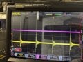
However, when I observe the output on the oscilloscope, the output signal (purple) differs from the filtered input signal (yellow):
I know that the amplification is limited by the power rails (±5 V), but even when I increased the supply to ±10 V or ±15 V, the output signal still looked the same.
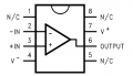
I also made sure the gain is above 2, as stated in the LM7171 datasheet for stability in non-inverting configurations.
I’ve added decoupling capacitors, but they had no noticeable effect.
Please, anyone have any idea? Thanks!
I'm building a non-inverting amplifier, where the goal is to amplify a 32 MHz low-passed-input signal. 1kΩ fixed resistor, and a variable resistor with max of 10kΩ.
The original signal is a 100 ps pulse at 500 kHz, connected to a photodiode (PDA10A2). This is then passed through a commercially available 32 MHz low-pass filter (Mini-Circuits – 32 MHz, 50 Ω | SLP-30+), which filters out high frequencies. The output from this filter is connected via a probe to the input of my amplifier circuit.
However, when I observe the output on the oscilloscope, the output signal (purple) differs from the filtered input signal (yellow):
- The amplitude drops significantly. I expected it to increase due to amplification. Even when the potentiometer is turned to maximum, the output remains low. If the potentiometer is at a value none other than the maximum, no signal appears at all. At this point i dont even know if the pueple waveform is indeed an output or just noise.
- The waveform shape changes slightly. I was expecting a similar shape to the input, just amplified.
I know that the amplification is limited by the power rails (±5 V), but even when I increased the supply to ±10 V or ±15 V, the output signal still looked the same.
I also made sure the gain is above 2, as stated in the LM7171 datasheet for stability in non-inverting configurations.
I’ve added decoupling capacitors, but they had no noticeable effect.
Please, anyone have any idea? Thanks!
Attachments
-
 60.5 KB Views: 13
 -
3.8 MB Views: 4
-
4.7 MB Views: 4
-
 1.4 MB Views: 11
 -
 10.7 KB Views: 12
 -
 56.8 KB Views: 11


