Facebook
 Google
 GitHub
 Linkedin
Hi everyone,
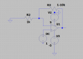
I'm very new to electronics world and would like to build a basic non-inverting amplifier using the LM7171 BIN op-amp. My goal is to amplify a 1V DC input, and I'm using a simple feedback configuration: a fixed 1kΩ resistor from input to ground, and a 10kΩ potentiometer from output to the inverting input.
The problems are:
1. Output Doesn't Vary with Potentiometer
When I turn the potentiometer, the output doesn’t change — it stays at around 1V, matching the input. Only when I rotate the pot all the way to max (10kΩ) do I get an output of ~5V, which I assume is due to gain clipping (my supply is ±5V).
But I expected a gradual increase in gain/output as I adjusted the pot. For example, halfway (~5kΩ) should give a gain of 6 and ~6V output (before clipping), but it still reads only 1V.
2. Op-Amp Overheats at Higher Supply Voltages
When I increase the supply from ±5V to ±10V or ±15V, the op-amp gets very hot, even if there's no signal input.
I verified the power pins are correctly connected, and my soldering is clean — no bridges or shorts.
The datasheet says the LM7171 supports up to ±15V, so I’m not sure why this is happening.
I tried adding decouplig caps of 0.1 uF and 10 uF from +V to GND and -V to GND but it deosnt help.
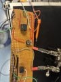
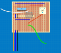
Please could anyone help me please? Attached you can find the circuit on a veroboard and also the schematic. Thanks!
Please ignore everything starting from the grey wire, they are a previous circuit that I already get rid of!
I'm very new to electronics world and would like to build a basic non-inverting amplifier using the LM7171 BIN op-amp. My goal is to amplify a 1V DC input, and I'm using a simple feedback configuration: a fixed 1kΩ resistor from input to ground, and a 10kΩ potentiometer from output to the inverting input.
The problems are:
1. Output Doesn't Vary with Potentiometer
When I turn the potentiometer, the output doesn’t change — it stays at around 1V, matching the input. Only when I rotate the pot all the way to max (10kΩ) do I get an output of ~5V, which I assume is due to gain clipping (my supply is ±5V).
But I expected a gradual increase in gain/output as I adjusted the pot. For example, halfway (~5kΩ) should give a gain of 6 and ~6V output (before clipping), but it still reads only 1V.
2. Op-Amp Overheats at Higher Supply Voltages
When I increase the supply from ±5V to ±10V or ±15V, the op-amp gets very hot, even if there's no signal input.
I verified the power pins are correctly connected, and my soldering is clean — no bridges or shorts.
The datasheet says the LM7171 supports up to ±15V, so I’m not sure why this is happening.
I tried adding decouplig caps of 0.1 uF and 10 uF from +V to GND and -V to GND but it deosnt help.
Please could anyone help me please? Attached you can find the circuit on a veroboard and also the schematic. Thanks!
Please ignore everything starting from the grey wire, they are a previous circuit that I already get rid of!
Attachments
-
 71.5 KB Views: 24
 -
 44.1 KB Views: 24