 Facebook
 Google
 GitHub
 Linkedin
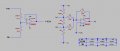
I built this circuit just out of interest and it doesn't behave as expected
i was of the understanding that the inverting summing amplifier would output the sum of two inputs and then invert the result which when i make R6 2k happens but if i make R6 110R i get a result that doesn't make any sense, can someone shine a light on what is going on here, my math isn't very good since i have ADHD so i might be missing something obvious
My readings are all taken relative to the virtual ground (+4.5v pin 3 of the LM358).
Attachments
-
 14.7 KB Views: 37


