Inverting summing amplifier help please?

Thread Starter

Homebrew1964

Joined Nov 22, 2024
105
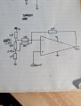
I built this little circuit again just to fill in some spare time and i am getting weird results, firstly and most importantly i think is i am getting a positive output when it should be negative and secondly the input voltages don't add up at the output.....any idea's anyone?

My negative probe is on pin 4 of the op amp for all readings.
 

Attachments

Papabravo

Joined Feb 24, 2006
22,058
Your schematic is deficient! It does not identify the opamp you are using. You also must realize that you can't get negative voltages when using a single power supply. In order to do that you need both positive and negative power supplies.

The reason the opamp you are using is important is that not all opamps operate over a given voltage range. For example the µA741 WILL not operate poperly with a single supply of +9VDC. This information is contained in the datasheet.

Lastly if you intend to operate with a single supply then it is common to have your analog "zero" point at Vcc divided by two. That way a "positive" result will be any voltage greater than Vcc/2 and a "negative" voltage will ve any voltage less than Vcc/2
 

Thread Starter

Homebrew1964

Joined Nov 22, 2024
105
Your schematic is deficient! It does not identify the opamp you are using. You also must realize that you can't get negative voltages when using a single power supply. In order to do that you need both positive and negative power supplies.

The reason the opamp you are using is important is that not all opamps operate over a given voltage range. For example the µA741 WILL not operate poperly with a single supply of +9VDC. This information is contained in the datasheet.

Lastly if you intend to operate with a single supply then it is common to have your analog "zero" point at Vcc divided by two. That way a "positive" result will be any voltage greater than Vcc/2 and a "negative" voltage will ve any voltage less than Vcc/2
I am using an LM358 which i am powering with a split supply, pin4 is at 4.5V relative to my virtual ground, pin 8 is at supply voltage of 9V, i can't understand why my output is positive and not inverted since i am feeding my inputs to the inverting input.
 

panic mode

Joined Oct 10, 2011
4,864
as stated, for this setup, your opAmp needs negative supply.

the best thing to avoid confusion is to call the voltages what they are - relative to "ground". makes no difference if that ground is a virtual ground.
it is not 0V, 4.5V and 9V. it is -4.5V, 0V and +4.5V.

so your opamp pin 4 must be connected to -4.5V, not to 0V.
so if your input voltages are positive (relative to virtual ground) their sum is also positive and the OpAmp output will go to negative side (below virtual ground).

OpAmp output cannot get higher than positive rail or lower than negative rail ... at least not voluntarily.
in present condition that means output will try to get to negative side but since pin4 is tied to 0V, the lowest it can get to is a smidge above 0V.
 
Last edited:

Thread Starter

Homebrew1964

Joined Nov 22, 2024
105
as stated, for this setup, your opAmp needs negative supply.

the best thing to avoid confusion is to call the voltages what they are - relative to "ground". makes no difference if that ground is a virtual ground.
it is not 0V, 4.5V and 9V. it is -4.5V, 0V and +4.5V.

so your opamp pin 4 must be connected to -4.5V, not to 0V.
so if your input voltages are positive (relative to virtual ground) their sum is also positive and the OpAmp output will go to negative side (below virtual ground).

OpAmp output cannot get higher than positive rail or lower than negative rail ... at least not voluntarily.
in present condition that means output will try to get to negative side but since pin4 is tied to 0V, the lowest it can get to is a smidge above 0V.
ok thankyou....i'll go check some voltages again.
 

Thread Starter

Homebrew1964

Joined Nov 22, 2024
105
Ok so i went and checked my input voltages and they are both negative relative to my virtual ground so that makes sense now why i am getting a positive output.

thanks for your help.
 

panic mode

Joined Oct 10, 2011
4,864
you are welcome. and since LM358 has two opamps you can use one of them to make better virtual ground (lower impedance).
1774477488616.png

not sure what you are after. if you are testing, this is probably much easier to work with:
1774477699369.png
 

Danm1

Joined Jul 19, 2010
75
Did I miss it, did you simulate with spice or LTspice?
I could try it for you since I have already with the LM358
For me it's always better to simulate before building the actual circuit, I've fried a few parts in my time.
 
Last edited:

Thread Starter

Homebrew1964

Joined Nov 22, 2024
105
Did I miss it, did you simulate with spice or LTspice?
I could try it for you since I have already with the LM358
For me it's always better to simulate before building the actual circuit, I've fried a few parts in my time.
I find actually building the circuit then testing to be more fun, frying components is a fun way to learn lessons :p
 

panic mode

Joined Oct 10, 2011
4,864
for opamps that is true, but who is to say that one may stop there? i have seem many parts blow up to bits and pieces (mosfets, diodes, capacitors...)
 

Thread Starter

Homebrew1964

Joined Nov 22, 2024
105
Oh and leds...yes leds can self destruct quite spectacularly on 9V without a protection resistor i found out when i started electronics way back when, they actually smell quite good when they do that :oops:
 
Top