Thks Ian0. Let me recap. You're suggesting, I should keep the circuit as is. Replace U1.2 w/ a proper comparator (LM339?) connected to a push-pull. As I understand, the output will be a square wave with variable duty cycle from the 10k-pot. right? As for the fan, I think it will be alright.
If you've already got started, I'd leave it alone, on the grounds that it will work "well enough", but if you are starting from scratch, I'd use a comparator with a push-pull output (not an LM339 because that has an open collector output) and I'd get a better op-amp (one with rather less offset voltage) for the thermocouple amplifier.
It is not a PWM circuit, per se, because that would involve a comparator and a ramp. This is closer to a comparator circuit with zero hysteresis (which would oscillate madly when it was at the operating temperature) but with a time constant (provided by the RC network) which enforces both a minimum off time and a minimum on time, the result being that when it is at the operating point it will turn on and off at the minimum times which looks as though it is a PWM circuit.
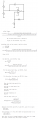
Thks Ian0 !! @crutschow. kindly provide me an LTspice simulation of circuit4.png, which is a diagram of U1.2 comparator stage. Vref is from the amplif. of thermocouple sensor voltage in U1.1 of LongTech_HotAir.png (post #12). Use what you think is an appropriate value for Vref. Thanks in advance !!!
The circuit in Figure 9 would probably not work because as we can see from Figure 10, the non-inverting input goes much higher than the power supply rails. It would probably either blow out or distort the exponential and the square wave output, thus making it pretty nasty.
To calculate the timings you have to be able to analyze an RC circuit where the capacitor has some initial voltage. That's because the capacitor will have some charge left when the output changes state. The charging exponential for the RC circuit with no initial voltage is:
Vc=Vcc*(1-e^(-t/RC))
and with initial voltage Vc0:
Vc=(Vcc-Vc0)*(1-e^(-t/RC))+Vc0
where RC=R*C.
That may help here.
If discharging, then:
Vc=Vc0*e^(-t/RC)
However, if Vc0 is greater than Vcc then we can also use this for discharging:
Vc=(Vcc-Vc0)*(1-e^(-t/RC))+Vc0
In fact, if we set Vcc=0 then we get the simpler one above:
Vc=Vc0*e^(-t/RC)
If they made a conscientious decision to go with that design rather than a more common one, then they were probably after better output control. This one could have better duty cycle control. That's once we get a working design.
In the hot air product they are using the workhorse LM358, that's nice to see
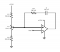
Ok here's the simpler solution. It assumes ideal components as usual, but we can always change that.
I figured it would be better to post the solution in image form rather than type it out here so see the attachment (C=C1 in the formulas).
The power supply voltage Vcc is E1, and the output of the opamp/comparator is E2. Later in the image we set E2 to ether +E1 or -E1 which means the opamp/comparator would have an ideal output of plus and minus the supply voltage, but we could always change that to maybe +14v and -14.5v or something like that.
The DutyCycle given is when a=1, which means R2=R1. If a is not equal to 1 then it is more complicated:
DutyCycle=log((b-a)/((a+2)*b+1))/log((b^2+2*b-a^2-2*a)/((a+2)^2*b*(b+2)+2*a+3))
There is a problem with the theory vs the practicality with this circuit though, and that is that the opamp/comparator inputs may clip the signal that would normally appear there and does actually appear in the pure theory model. That's also the case in the paper that was presented earlier in this thread though so I went with it. We can change that if needed or add more components.
This circuit was a little more interesting than the usual Resistor charging the grounded Capacitor oscillator circuit.
 Facebook
 Google
 GitHub
 Linkedin
")