Once the Q2 is removed, I was able to connect the both wires from the video doorbell with the breadboard without activating the doorbell. But none of the buttons activated the other system.
Yes. But as I hadn’t connected the 230v side correctly, I was testing it by powering the 230v opto-isolater continuously with AC current. if it was not powered with AC current, video doorbell was activated without pressing its button.
Later I realised, in the real scenario opto-isolator would only be activated by pressing the wall switch.
That doesn't seem right it should have been just the opposite. May have a bad transistor.
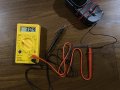
Remove Q2 and leave Q1 installed. Measure the voltage on the output of the video button, should have appx 3 volts.
The voltage at the red arrow junction should be appx 0 volts.
That doesn't seem right it should have been just the opposite. May have a bad transistor.
Remove Q2 and leave Q1 installed. Measure the voltage on the output of the video button, should have appx 3 volts.
The voltage at the red arrow junction should be appx 0 volts. View attachment 298834
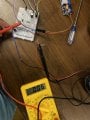
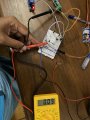
The voltage between the video doorbell button wires is still 3.06v and the voltage at the red arrow in reference to the negative wire of the 5v supply is almost 0.0v. The voltage at the same point in relation to the negative wire of the video doorbell is also 0v. (Images are attached).
Once I changed the direction of the diode, relay got activated and then deactivated in a around 2 seconds. But then I saw there is a 5v at the red arrow. And at that time, pressing the video doorbell button did not activate the relay. All these was done removing Q1 and Q2.
When only the Q1 is in place with reversed diode, relay keeps activated all the time.
 Facebook
 Google
 GitHub
 Linkedin