Need help to make two doorbells work simultaneously

Thread Starter

Anomajaya

Joined Jul 11, 2023
59
OK.

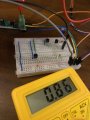
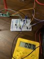
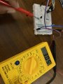
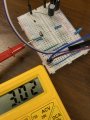
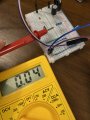
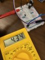
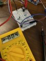
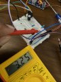
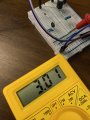
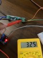
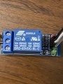
Now it appears Q1 is defective or installed incorrectly. Should read 3 volts on the Gate and 0 volts on the Drain if good and installed correctly.
I checked the Q1. As you mentioned there is 3v at Gate and 0v at Drain. These were measured while the diode was in the correct direction. In this setup though I pressed the doorbell button or the wall switch, relay didn’t work. (I have not connected the Q2).

Once the diode was reversed, the relay kept activated continuously and the Q1 Gate and Drain had 0v.
 

Attachments

Thread Starter

Anomajaya

Joined Jul 11, 2023
59
I'm not sure what's going on but the circuit works perfectly on my breadboard.
Can you get me some more voltage readings on Q1?
Yes, I’m more than happy to. Please see the attached photos.
If you could share a photo of your breadboard, I’ll try to replicate it to see exactly similar. Then you can easily go through the circuit.
 

Attachments

sghioto

Joined Dec 31, 2017
8,634
I see several voltages that should not be there. Going to have to step back and do this one stage at a time.
Are you sure the jumper on the relay module is set for HIGH?
 

Thread Starter

Anomajaya

Joined Jul 11, 2023
59
I see several voltages that should not be there. Going to have to step back and do this one stage at a time.
Are you sure the jumper on the relay module is set for HIGH?
Currently I’m using a 5v relay with no jumpers and it’s little different that the schematic diagram posted in post #1.
I hope the current one is by default set for High. Is there any way to check it?
 

Attachments

sghioto

Joined Dec 31, 2017
8,634
Take the wire on the input to the module and connect it to the negative and see if it activates. If it does it set for a LOW trigger.
If it is a LOW trigger the circuit is easily modified for that module.
 
Last edited:

Thread Starter

Anomajaya

Joined Jul 11, 2023
59
Take the wire on the input to the module and connect it to the negative and see if it activates. If it does it set for a LOW trigger.
If it is a LOW trigger the circuit is easily modified for that module.
Yes. It activates once I connected th IN cable to 5v negative side and keeps inactive for the 5v positive.
 

Thread Starter

Anomajaya

Joined Jul 11, 2023
59
I am tempted to to send this guy a working assembled circuit just to end this thread.
You are most welcome sending me a assembled circuit. And my apologies on the lengthy thread. As you already know I’m not in to electronics in my profession though I’m trying to learn it as I’m fascinated by electronics. So please bear with me.
:)
 

Thread Starter

Anomajaya

Joined Jul 11, 2023
59
New version using LOW trigger relay module.
Suggest not connecting Q3 until you have Q1 and Q2 circuit working. Work in stages please and report.

View attachment 298927
Thank you.

Without the Q3, system works perfectly. Once I press the video doorbell button, relay is activated. (Video).

But when the Q3 is inserted, video doorbell button is activated without pressing it. Moreover, the relay is also active even without pressing either buttons.
 

sghioto

Joined Dec 31, 2017
8,634
That's because there is voltage on the output of the opto isolator even when the doorbell button is not pressed. I see 3.25 volts in the photo in post #105. Try changing R3 to a 10K resistor.
 
Last edited:

BobTPH

Joined Jun 5, 2013
11,523
Sound like the problem is that we din’t have the video doorbell button characterized correctly, thus @sghioto cannot test the circuit.

I think this would help:

Measure the voltage across the video doorbell button leads.

Then do the 3 more measurements with 3 different resistors across them, 100, 1K, and 10K. This would help us understand how the button is wired.
 

Thread Starter

Anomajaya

Joined Jul 11, 2023
59
That's because there is voltage on the output of the opto isolator even when the doorbell button is not pressed. I see 3.25 volts in the photo in post #105. Try changing R3 to a 10K resistor.
Once I replace R3 with 10k resistor still the relay keeps activated. Then there is a voltage of 0.86v at the output of the opto isolator.
 

Attachments

sghioto

Joined Dec 31, 2017
8,634
Try a 1K resistor.
Q3 may be bad also as my test show the 2N7000 requires appx 2 volts at the gate for 0 volts at the drain in this application.
 
Last edited:
Top