Facebook
 Google
 GitHub
 Linkedin
MisterBill2
- Joined Jan 23, 2018
- 27,870
I suggest, on the circuit drawing, avoid using any "ground" symbol for any part that does not actually require an actual ground connection.Try this circuit with the 2N7000.
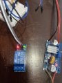
When the button is pressed for the 230 volt bell the opto-isolator turns on Q2 which shorts the switch wires on the video doorbell which in turns activates the 5 volt relay module to power the 230 volt doorbell.
View attachment 298675
The reason for the suggestion is that really, none of the system requires any sort of external "ground" connection. So using the symbol instead of showing a connection can cause confusion for those not masters of the concepts.
And certainly creating the functionality of two inputs in parallel when they are so very different is a really "big deal", and leading another through the process is certainly quite a task.
So my suggestion is only to prevent confusion.


")