Now you need to build a jig and test all of them. You'll be lucky if they're even 555 timers. The counterfeiters only care about package.
Can you post some well focused high resolution of some of the parts? You can usually tell if they've sandblasted the top and remarked. You shouldn't see any pitting on the shoulders of the leads.
I'd use Jameco, Newark, Mouser, or Tayda. A lot of people like DigiKey, but, for some reason, I don't. I'm of the opinion that their prices are higher because they carry a large inventory.
Don't buy from Ali Express, Banggood, or any place in China. You're almost guaranteed to get counterfeit parts.
Fantastic. They're probably inaccurate. These came in my breadboard kit and I've been using the labels on the bags for reference. I have no way of confirming the resistance until I get my multimeter in. I'm ordering new ICs from mouser and I'll have a oscilloscope and multimeter this weekend and I'm just going to start from the top.
Not trying to waste anyone's time being the noob I am
2k = red black black brown (2 0 0 1 = 200 * 10^1)
100k = brown black black orange (1 0 0 3 = 100 * 10^3)
1% resistors use a 5 band code.
Sometimes it's difficult to tell which end to start reading from, but there are some numbers that aren't valid in certain positions and that gives you a clue.
Put the 10μF in between Vcc and GND and leave it in permanently. It is a required part of the circuit. You don't have an option.
Does the circuit function correctly with it in place?
Now you need to build a jig and test all of them. You'll be lucky if they're even 555 timers. The counterfeiters only care about package.
Can you post some well focused high resolution of some of the parts? You can usually tell if they've sandblasted the top and remarked. You shouldn't see any pitting on the shoulders of the leads.
Ace isn't on my list for electronic components.
I'd use Jameco, Newark, Mouser, or Tayda. A lot of people like DigiKey, but, for some reason, I don't. I'm of the opinion that their prices are higher because they carry a large inventory.
Don't buy from Ali Express, Banggood, or any place in China. You're almost guaranteed to get counterfeit parts.
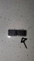
Best I could get with the lighting and my phone sorry.
Left is the original 555 that I got and i had effed up and shorted out. Now it gets extremely hot when plugged in. So I got a set (right) which closer inspection it doesnt look pitted but it does look scraped in some way. You can tell an obvious difference in quality. I'm marking this as faulty equipment because inhave no way of proving other wise and I've tried EVERY astable setup I've found on line with EVERY combination of resistors I have. And it does not give me any useable clock pulse.
Put the 10μF in between Vcc and GND and leave it in permanently. It is a required part of the circuit. You don't have an option.
Does the circuit function correctly with it in place?
Sometimes it's difficult to tell which end to start reading from, but there are some numbers that aren't valid in certain positions and that gives you a clue.
This matches the chart provided with my resistors and I'm looking and seeing that the labels do not match up.. I'm gonna give this a rest until I get some way to verify with my multimeter.
With all of this shoot through and decoupling cap back and forth, I decided to do a test.
I breadboarded a 555 timer (TI NE555P) using 4.7k resistors and a 220uF cap that I had handy. That should give me a frequency of about 0.5Hz.
The circuit is working using a bipolar timer, a 5.2V supply with around 40mV of ripple, and no supply bypass cap. A cap on the supply won't hurt, but in my case, it's unnecessary.
I put my DSO138 on the timing cap and the scope doesn't load the node appreciably. You can see that the capacitor voltage varies between 1/3 and 2/3 of VCC as expected. The scope is by no means what I'd call "good", but it's sufficient and saves wear and tear on my vintage Tek CRT scopes.
Sorry for the crappy image. I needed flash and didn't want the glare on the screen, so I took it at an angle.
With all of this shoot through and decoupling cap back and forth, I decided to do a test.
I breadboarded a 555 timer (TI NE555P) using 4.7k resistors and a 220uF cap that I had handy. That should give me a frequency of about 0.5Hz.
The circuit is working using a bipolar timer, a 5.2V supply with around 40mV of ripple, and no supply bypass cap. A cap on the supply won't hurt, but in my case, it's unnecessary.
I put my DSO138 on the timing cap and the scope doesn't load the node appreciably. You can see that the capacitor voltage varies between 1/3 and 2/3 of VCC as expected. The scope is by no means what I'd call "good", but it's sufficient and saves wear and tear on my vintage Tek CRT scopes. View attachment 216770
Sorry for the crappy image. I needed flash and didn't want the glare on the screen, so I took it at an angle.
The highest cap I have currently is 100uf. And to be clear your using 2 - 4.7k resistors for the timing? I noticed a difference last night when I used two of the same resistance resistors but it still was not an reasonable cycle. I believe it would have been about a 90% duty cycle? On for 90% of the time and just a quick flicker off. Correct me if I'm wrong. That's just what my eyes were seeing
Guess no one uses real cameras these days. A clearly focused picture with a large F-stop would give a good depth of field.
That's the saddest TI logo I've ever seen. Both appear to be counterfeits. If you look at the texture on top, bottom, and sides, it should be uniform because the package is molded. The leads should be shiny; yours look like they might be textured from sand blasting.
Here's an authentic part from the late 70's/early 80's:
Use 2 10k resistors and the frequency will be
\( f=\frac{1.44}{(R_A + 2R_B)C}=\frac{1.44}{30k*100uF}=0.48Hz\)
You could have determined that the frequency would be about the same because you'd be doubling the resistance and halving the capacitance.
No supply bypass cap and no cap bypassing the control pin to ground. Both are recommended, but clearly not mandatory in all cases.
I noticed a difference last night when I used two of the same resistance resistors but it still was not an reasonable cycle. I believe it would have been about a 90% duty cycle?
I have learned that upon receiving ICs from Amazon, fleaBay, or AliX that I have to test them. One batch of 15 555s had over half of them fail using a simple test circuit. They did reimburse me for the entire lot but it is the price you pay for cheap components.
Guess no one uses real cameras these days. A clearly focused picture with a large F-stop would give a good depth of field. View attachment 216778
That's the saddest TI logo I've ever seen. Both appear to be counterfeits. If you look at the texture on top, bottom, and sides, it should be uniform because the package is molded. The leads should be shiny; yours look like they might be textured from sand blasting.
Lol my only camera is from 2005 would be much worse lol. And yeah they are definitely matt/satin not shiny. The ones on the right actually have excess plastic molding at the seem on some of them. Starting to really believe these are my issue. Very frustrating but I have 10 coming from mouser on friday
Thankyou everyone! I'm honestly surprised I found this much support this quickly trying to help me out. I'll probably be here often I have new chips coming from mouser friday with oscilloscope and hopefully I can get somewhere with those. Also picked up a bunch of logic chips so I'm happy bout that. And honestly i think I've learnt so much more the past few days not getting anything to work than I would have if it worked the first go. Really looking forward to future projects! Thanks!
 Facebook
 Google
 GitHub
 Linkedin


 I have new chips coming from mouser friday with oscilloscope and hopefully I can get somewhere with those. Also picked up a bunch of logic chips so I'm happy bout that. And honestly i think I've learnt so much more the past few days not getting anything to work than I would have if it worked the first go. Really looking forward to future projects! Thanks!


