Hello,
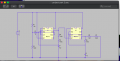
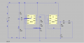
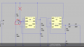
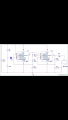
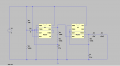
I can't seem to see why the R7 resistor is not showing a current. I've redone the circuit three times and I'm still not getting any result. Is it something to do with the program? I've attached the LTspice file, the circuit diagram, and my simulation results. If anyone can help that would be great. Thanks.
I've replaced the LDR and Buzzer with 1000 ohm resistors.
Attachments
-
2.5 KB Views: 9
-
 311.6 KB Views: 22
 -
 22.9 KB Views: 21
 -
 23.3 KB Views: 17