Facebook
 Google
 GitHub
 Linkedin
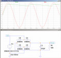
hi,The next question is to double the C value and see what happens to ripple voltage and find a relationship between the C value and the Vpk at diodes...
When doubling the smoothing capacitance you should also exam what increase you have in the charging current thru the diodes at and near Vpeak.
Also measure the increased V drop across the diodes at the higher pulse currents
E