LTSpice - How to add new Diode

ericgibbs

Joined Jan 29, 2010
18,766
One more question:

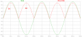
I know i can use the cursors 1 & 2 to compare 2 values. But How can i see the defference (subtraction operation) between cursor 1 and cursor 2 when they are in different curves in the plot?
hi,
I do not fully understand your question.?

You can right click on the plot window and select 'Add Trace' from the drop down menu.

Enter the required plot data in the lower text box, use the plot data shown in the bigger window to create the equation.
 

Thread Starter

PsySc0rpi0n

Joined Mar 4, 2014
1,755
What i need is to measure the potential drop down in the diodes which can be measured placing a cursor at the top of the Vin curve and another cursor at the top of the Vout curve at the same time point, let's say 5ms. I need to know that small drop that should be the diode reference voltage of around 0.7V...
 

ericgibbs

Joined Jan 29, 2010
18,766
What i need is to measure the potential drop down in the diodes which can be measured placing a cursor at the top of the Vin curve and another cursor at the top of the Vout curve at the same time point, let's say 5ms. I need to know that small drop that should be the diode reference voltage of around 0.7V...
This shows the Vdiode voltage drop.

NOTE: with a full bridge rectifier you will have 2 diode voltage drops between the Vin and rectified out.
 

Attachments

Thread Starter

PsySc0rpi0n

Joined Mar 4, 2014
1,755
Ah, ok... Thank you!

My time has been short to do all this jobs our tutors asks us.

Well, now I'm trying to get the behavior of a zener! But looks like something's wrong.

Should it look like this?
 

Attachments

ericgibbs

Joined Jan 29, 2010
18,766
Ah, ok... Thank you!

My time has been short to do all this jobs our tutors asks us.

Well, now I'm trying to get the behavior of a zener! But looks like something's wrong.

Should it look like this?
Hi,
The resistor and diode should be swopped over, ie: exchange their locations.

EDIT:
You could plot Vout to Vin, using the two probe method
 

Attachments

Thread Starter

PsySc0rpi0n

Joined Mar 4, 2014
1,755
Let me see if I understood.

What i have measured in my plot was only the Vout.

Then you used the same schematic but switched both probes so that the plot would be in the right position, was that it?
 

ericgibbs

Joined Jan 29, 2010
18,766
Let me see if I understood.

What i have measured in my plot was only the Vout.

Then you used the same schematic but switched both probes so that the plot would be in the right position, was that it?
Yes, I have shown both methods.

Switching the probes for plotting the voltage across the zener and also swopping the zener/resistor positions and plotting Vout to Gnd [ ie: across the zener to 0V/Gnd]
 

Thread Starter

PsySc0rpi0n

Joined Mar 4, 2014
1,755
Ok...

Tell me, please, the major difference between using diodes for rectify waves or use zeners to do the same.
Don't need a thorough explanation, just the headlights, please! Or point me somewhere where i can read about it!
 

crutschow

Joined Mar 14, 2008
34,285
Zener diodes are normally used where a fixed voltage is desired and normal diodes are used for rectification.

The difference is that the specified zener breakdown voltage has a relatively tight tolerance on the upper and lower value around its voltage rating. A normal diode's specified voltage is the minimum breakdown voltage but an individual diode can have a breakdown voltage much higher than this (no specified upper limit).
 

Thread Starter

PsySc0rpi0n

Joined Mar 4, 2014
1,755
Hi once more.

Thanks for the help given so far...

Now I'm studying filtered rectifiers... I don't know if this is the correct term.

It's a bridge rectifier but with a capacitor. I still don't know how to calculate the capacitor value so that I can get the ripple at 9% of it's max value.
 

ericgibbs

Joined Jan 29, 2010
18,766
Hi once more.

Thanks for the help given so far...

Now I'm studying filtered rectifiers... I don't know if this is the correct term.

It's a bridge rectifier but with a capacitor. I still don't know how to calculate the capacitor value so that I can get the ripple at 9% of it's max value.
hi,
You could use LTSpice to confirm any calculation.

You have to know the mains frequency, full or half bridge rectifier and the resistive load.
Knowing these you can calculate the required smoothing capacitor for the ripple percentage.

E.
 

Jony130

Joined Feb 17, 2009
5,487
The simplest way to find capacitor values is to use this equation
C = Q/V = (I*t)/V

I - load current
t - discharge time 1/50Hz (20ms) for half wave rectifier and 1/100Hz (10ms) full wave rectifier or 1/60Hz and 1/120Hz for countries with 60Hz mains.
V - capacitor ripple voltage
 

ericgibbs

Joined Jan 29, 2010
18,766
hi,
In your circuit you have D3 and D4 shorted to 0V, so you only have half wave rectification.

Look at this image, remember what I said about COM.:)

Use Jony's formula to give you the C smoothing in Farads

E

Dont forget the V value in the V1 source 50Hz, Vpeak.!!
 

Attachments

Thread Starter

PsySc0rpi0n

Joined Mar 4, 2014
1,755
hi,
In your circuit you have D3 and D4 shorted to 0V, so you only have half wave rectification.

Look at this image, remember what I said about COM.:)

Use Jony's formula to give you the C smoothing in Farads

E

Dont forget the V value in the V1 source 50Hz, Vpeak.!!
I think I asked you some posts ago to explain me again that matter about the COM because I haven't understood it.:(

I can't also understand what happends to the Source Voltage! Also the resistor we should simulate is of 330 ohms, so How can I calculate C through that formula that Jony130 said?
 
Top