Ok, let me kinda study your english because i'm struggling to keep up with those technical terms. I'm sorry, i'm not english as you probably already realised!
Ok, let me kinda study your english because i'm struggling to keep up with those technical terms. I'm sorry, i'm not english as you probably already realised!
Run the sim.
Right click on the Plot window, a drop down menu will appear.
Select 'Add Plot Pane'
To move a Plot trace from window to another, place your cursor on the Data Label, just above the plot trace, keep the left mouse key down and drag the label to another plot window/pane.
Thanks for replying... You're being a great help to me... I'm just starting to learn the basics. It's the very first time I'm dealing with this type of stuff (electronic stuff)...
The exercise asks that we plot the zener diode caracteristc curve with direct polarization and inverse polarization. So i need to do both.
I know when it is deirectly polarized, it behaves just like 1N4001, but it is diferente when in inverse polarization!
Things might be jsut getting more exciting now but also more complex...
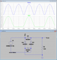
I'm trying to analyse a full wave rectifier.
But I don't know if the plot is correct because I can't understand why the Vin doesn't go up to 6V and down to -6V and also why between 10 and 20ms the Vin is ≈ -0.7V.
Things might be jsut getting more exciting now but also more complex...
I'm trying to analyse a full wave rectifier.
But I don't know if the plot is correct because I can't understand why the Vin doesn't go up to 6V and down to -6V and also why between 10 and 20ms the Vin is ≈ -0.7V.
But this is only half cycle, correct? Can we observe the entire wave at the same plot Or do we have to simulate 2 different schematics to view the other half-cycle?
But this is only half cycle, correct? Can we observe the entire wave at the same plot Or do we have to simulate 2 different schematics to view the other half-cycle?
RUN the sim!!
Place the cursor on the Vin on the circuit, a red probe will appear,,keep the mouse left key pressed down, now slide the cursor down to the COMMON symbol [ near the 10meg] a second 'probe' will appear, this will plot the full input sine wave when you release the mouse key.
Can you explain me a bit better the common symbol, the ground and the 10MEG resistor?
The schematic I have from my tutor has the ground next to the resistor. Why it doesn't work like that and or/why do he has the ground next to resistor!
Yes i have... And thank you for the rest of the explanation...
I still don't fully understand it but i get an idea. I'm completelly new to electronics and LTSpice, so i tend to get conffused yet with some concepts we need to know to understand some basic things.
I'm going to perform now some simulations for half and full wave rectifiers and bridge rectifiers with middle common point... I don't know how to say it correctly in english...
I know i can use the cursors 1 & 2 to compare 2 values. But How can i see the defference (subtraction operation) between cursor 1 and cursor 2 when they are in different curves in the plot?
Press keyboard F4, a small window will appear, type in the Node name you want.
If you want to be more exact , left click the 'What Type' on that small window,, choose the Node as an Input or Output type [ Its not essential that you do this, but on a big circuit the Node symbol will be more helpful]
Use F7 key to move the Mode name around the circuit.
 Facebook
 Google
 GitHub
 Linkedin
") No problem.
No problem.