Facebook
 Google
 GitHub
 Linkedin
Hi Everyone,
Curently i have a Tension Compression Load cells(attached datasheet) connected to a Electronic control system which Supply's voltage and calculate the force. Right now i need to send the raw data of the load cell to another complete diferent application.
Is there any interface to send the analog data(raw values) of load cell data to current PCB control system and to another application - Time synchronized by interface plug of high quality like stereo jack plug or DB9.
Thanks in advance
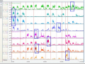
Attachments
-
355.7 KB Views: 5
-
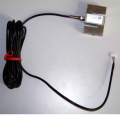 137.3 KB Views: 6