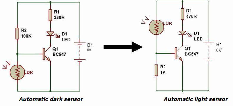
LDR working the opposite way

Thread Starter

zazas321

Joined Nov 29, 2015
936
Yeah im going to the shop tommorow to fix my multimeter. Yeah the current with this resistor is way too high. But if i have alot of LEDs like 50, and the current needed for the LEDs would be like 50* 20mA. i will get 1A. So in this case the resistor is not even neccesary cuase its like only 4-5 Ohms. Am i right? And how do i deal with different voltage of the different colour LEDs? i mean if i have 3 colour LEDs : red, green, and yellow. Is there are any possible, not problematic way to connect them in parallel in such way : red-green-yellw-red-green-yellow-red-green-yellow and so on.. Im affraid that some of the LEDs will light brightly and some of them wont light at all
 

dl324

Joined Mar 30, 2015
18,347
Yeah im going to the shop tommorow to fix my multimeter.
Something is wrong with your meter? What does this have to do with your LDR/LED problems?
Yeah the current with this resistor is way too high.
How is it way too high? 4mA is a reasonable current; depending on the brightness you desire. Brightness also depends on the luminous efficiency of the LEDs being used.
But if i have alot of LEDs like 50, and the current needed for the LEDs would be like 50* 20mA. i will get 1A. So in this case the resistor is not even neccesary cuase its like only 4-5 Ohms. Am i right?
You are wrong. You should take some time to study the basics or the reasons things work, or don't work, will be a mystery to you.
And how do i deal with different voltage of the different colour LEDs? i mean if i have 3 colour LEDs : red, green, and yellow. Is there are any possible, not problematic way to connect them in parallel in such way : red-green-yellw-red-green-yellow-red-green-yellow and so on.. Im affraid that some of the LEDs will light brightly and some of them wont light at all
This has been explained several times. If you don't understand, take a break from wiring things until you do. You'll find electronics a lot more enjoyable if you understand what you're doing.
 

Thread Starter

zazas321

Joined Nov 29, 2015
936
Something is wrong with your meter? What does this have to do with your LDR/LED problems?
How is it way too high? 4mA is a reasonable current; depending on the brightness you desire. Brightness also depends on the luminous efficiency of the LEDs being used.
You are wrong. You should take some time to study the basics or the reasons things work, or don't work, will be a mystery to you.
This has been explained several times. If you don't understand, take a break from wiring things until you do. You'll find electronics a lot more enjoyable if you understand what you're doing.
My multimeter is not functioning right. It doesnt show the right resistance.
I actually wanted to say that the current is too low for LED to light brightly, isnt it?

And about 50 LED in parralel i dont get it why i am wrong :(
 

dl324

Joined Mar 30, 2015
18,347
My multimeter is not functioning right. It doesnt show the right resistance.
For most circuits, using the resistor color code is sufficient.
And about 50 LED in parralel i dont get it why i am wrong :(
When you said the resistors weren't required after some questionable resistance calculation.

After you get your LDR circuit working, I suggest you do some study. Things will make more sense to you and it will be more enjoyable for you (and us).
 

Thread Starter

zazas321

Joined Nov 29, 2015
936
For most circuits, using the resistor color code is sufficient.
When you said the resistors weren't required after some questionable resistance calculation.

After you get your LDR circuit working, I suggest you do some study. Things will make more sense to you and it will be more enjoyable for you (and us).
Hehh :/ I calculated that if i need 1A of current and i have for example 4.5V so the resistor would be 4,5Ohms. So i would need to add 50 resistors to each LED for circuit to work correctly..

Yeah and about the LDR circuit.. Im currently working to understand it. But i dont understand one thing.. When there is light, the resistance of the LDR will be very low and most of the current will go throught the LDR so the LED will not glow.. As the light fades, the resistance is getting higher and higher, so at some point the resistance will be high enough and the current will choose the easier way and will travel to the LED side and light the LED up. But i guess i understand the circuit wrong, because if it was like i said, the transistors would not be needed.
 

dl324

Joined Mar 30, 2015
18,347
Hehh :/ I calculated that if i need 1A of current and i have for example 4.5V so the resistor would be 4,5Ohms. So i would need to add 50 resistors to each LED for circuit to work correctly..
There could be many issues with your circuit. For example, can the transistor you're using handle 1A. Will the saturation voltage be low enough to not affect the brightness you expect?
But i guess i understand the circuit wrong, because if it was like i said, the transistors would not be needed.
Exactly my point; it's clear that you don't understand what you're doing.

The LDR and resistor on the base of the NPN transistor form a voltage divider. When the voltage applied to the base of the transistor is around 0.7V, it will be on (saturated) and the LEDs will be at maximum brightness. The transistor will turn on before that and the LEDs will be dimly lit; but you're not that far yet.

When the transistor is used in it's "off" and "on" state, it it also referred to as a switch.
 

ian field

Joined Oct 27, 2012
6,536
Both of those arrangements work much better if you use the 2 transistor Schmitt trigger circuit.

Examples online aren't as plentiful as I would have expected - but they can be found with a bit of effort.

There's some nice examples in the archive of Radio Constructor magazine on americanradiohistory.com - but its rather a lot of magazines to search through looking for them!
 

Thread Starter

zazas321

Joined Nov 29, 2015
936
There could be many issues with your circuit. For example, can the transistor you're using handle 1A. Will the saturation voltage be low enough to not affect the brightness you expect?
Exactly my point; it's clear that you don't understand what you're doing.

The LDR and resistor on the base of the NPN transistor form a voltage divider. When the voltage applied to the base of the transistor is around 0.7V, it will be on (saturated) and the LEDs will be at maximum brightness. The transistor will turn on before that and the LEDs will be dimly lit; but you're not that far yet.

When the transistor is used in it's "off" and "on" state, it it also referred to as a switch.
Is there any way to calculate what voltage i will have on the base of transistor without multimeter?..
 

dl324

Joined Mar 30, 2015
18,347
Is there any way to calculate what voltage i will have on the base of transistor without multimeter?..
Did you give any thought to your question before posting?

To calculate the voltage on the base, you need to know the ratio of the two resistors in the divider. How can you know the resistance of two variable resistors without measuring something???
 

Thread Starter

zazas321

Joined Nov 29, 2015
936
Ok lets give the random numbers, if the resistor is 100k Ohms and LDR is at 50k Ohms so theese 2 resistors is in the divider, and the one to LED is lets say 500Ohms. And how about the current now? What would be the whole circuit current?
 

dl324

Joined Mar 30, 2015
18,347
Ok lets give the random numbers, if the resistor is 100k Ohms and LDR is at 50k Ohms so theese 2 resistors is in the divider, and the one to LED is lets say 500Ohms.
Do you mean this?
upload_2015-12-8_11-48-30.png
And how about the current now? What would be the whole circuit current?
The divider would try to put 1.5V on the base of the transistor, but the BE junction will limit it to 0.7V. That will saturate the transistor, so it's collector will be at approximately 0V. Assuming the LED would drop about 2V, that would put 2.5V across the 5K resistor. Since I = V/R, current would be 2.5V/5000 ohms = 0.5mA.
 

Thread Starter

zazas321

Joined Nov 29, 2015
936
Yeah i mean
Do you mean this?
View attachment 96175
The divider would try to put 1.5V on the base of the transistor, but the BE junction will limit it to 0.7V. That will saturate the transistor, so it's collector will be at approximately 0V. Assuming the LED would drop about 2V, that would put 2.5V across the 5K resistor. Since I = V/R, current would be 2.5V/5000 ohms = 0.5mA.
Yeah i meant something like that :eek:.Why the divider will try to put 1.5V if the power supply is 4.5V? :eek:.Is that something you cant calculate you just have to know?

I calculated abit on what resistor do i need if i want to mix the colours of the LED. So is my calculations right? :eek:
As shown on the LED packages i bought Red have 2.5V voltage drop, Green - 2.1V and Yellow - 2V
 

Attachments

Thread Starter

zazas321

Joined Nov 29, 2015
936
I wanted to ask one more question.. Is there any way to calculate the values when the voltage to the base will be 0.7 volts? Assuming that circuit will have 0,5mA current and so that LDR and 100K ohm resistor is in parralel with the battery so in both of theese should be also 4.5V. Am i right there? So how do i know with what LDR value there will be enough voltage to make the transistor working ( 0,7V)
 

dl324

Joined Mar 30, 2015
18,347
Why the divider will try to put 1.5V if the power supply is 4.5V? :eek:.Is that something you cant calculate you just have to know?
There's nothing mystical about it. You just use the voltage divider equation and some knowledge.

VLDR = 4.5V * RLDR / (RLDR + R1) = 1.5V
The current in the divider is ILDR = 4.5V / (RLDR + R1) = 0.03mA
(Tried using tex, but it was too finicky...)

At 20mA, the resistance of the B-E junction will be on the order of an ohm. Most of the current will go into the base of the transistor and the voltage will be limited to about 0.7V.

The resistance looking into the base of the transistor is something you learn. It's re (I pronounce it "little r e") and is about 25 ohms / Ie.

If you changed the values of the resistors so they were ohms instead of KΩ, say 1Ω and 0.5Ω; the current in the divider would be 3A. Using the same resistance for the B-E junction, 1A would go into the base; the transistor would be destroyed if it couldn't operate at that current.
I calculated abit on what resistor do i need if i want to mix the colours of the LED. So is my calculations right? :eek:
As shown on the LED packages i bought Red have 2.5V voltage drop, Green - 2.1V and Yellow - 2V
Your calculations are correct.

Operating your circuit from 4.5V is requiring you to use a lot of resistors. If you use a higher voltage, you can use a combination of series and parallel LEDs and reduce the number of resistors. With 4.5V, you could put 2 green or yellow in series. The red need to be singles; though 2.5V for red seems high.

Another option is to operate the LEDs at a voltage where the current limiting resistors would be very small and could be eliminated. This is commonly done in low voltage battery operated circuits to minimize wasted power. Using LEDs with different forward voltages precludes this option for you.
 
Last edited:

dl324

Joined Mar 30, 2015
18,347
Figured out what I was doing wrong...

\( \small V_{LDR} = 4.5V * \frac{R_{LDR}}{R_{LDR} + R_1} = 1.5V\)

The current in the divider is \( \small ILDR = \frac{4.5V}{R_{LDR} + R_1} = 0.03mA\)
 

dl324

Joined Mar 30, 2015
18,347
how do i know with what LDR value there will be enough voltage to make the transistor working ( 0,7V)
The transistor will start turning on before the B-E voltage is 0.7V. That value is what the voltage will be when the transistor is completely on.

Assuming a lower, starting to turn on, B-E voltage of 0.5V, when this equation is satisfied, LEDs will start turning on:

\( \small 4.5V * \frac{R_{LDR}}{R_{LDR}+R_1} = 0.5V \)

What transistor are you using for the switch? You want one that can handle 1A and have a low saturation voltage.
 

Thread Starter

zazas321

Joined Nov 29, 2015
936
The resistance looking into the base of the transistor is something you learn. It's re (I pronounce it "little r e") and is about 25 ohms / Ie.
Wow that some very usefull information! thanks. I understood most of it, just this part seems tricky for me. What do you exactly mean Ie? is that those 20mA?
and i didint quite catch why if we have lets say 3A in the divider, why only 1A will go into the base?
and im using BC547 transistor
 
Last edited:

dl324

Joined Mar 30, 2015
18,347
Wow that some very usefull information! thanks.
Your welcome. And if I was wrong, someone will correct it...
I understood most of it, just this part seems tricky for me. What do you exactly mean Ie? is that those 20mA?
Mostly. The transistor has 3 currents: Ib (base), Ic (collector), and Ie (emitter). The relationship is Ie = Ib + Ic. Further, the relationship between the currents is Ic = βIb and Ie = (β+1)Ib. Transistor β is a function of transistor geometries, chemistry, collector-emitter voltage, and current; to name a few. When a transistor is operated in it's saturation mode, β is typically reduced to a tenth of it's typical value.
and i didint quite catch why if we have lets say 3A in the divider, why only 1A will go into the base?
You use the current divider equation for parallel resistors. If you have 3A flowing through 0.5Ω||1Ω, 1/3 of the current will flow through the 1Ω and 2/3 will flow through the 0.5Ω.
 
Top