Control voltage not working

Thread Starter

Homebrew1964

Joined Nov 22, 2024
187
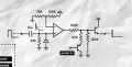
I'm not sure what this circuit is called but i built it as part of a percussion circuit (snare drum) but the problem i have is i am getting no signal after the input capacitor, i feed a 9V pulse into the capacitor expecting a signal going into pin 3 of the IC but i'm getting nothing, not even a blip, is this another bum circuit from the internet?
 

Attachments

WBahn

Joined Mar 31, 2012
32,814
Need a lot more detail, since that circuit isn't complete. You keep thinking that we have some crystal ball that allows us to peer over your shoulder or read your mind. We don't!

What opamp are you using?

Telling us that you expect something going into pin 3 of the IC is meaningless unless we know the pinout of the IC, which depends on which opamp you are using AND which package it is in. Is pin 3 the noninverting input of the opamp? Is it the output of the opamp? Either is a reasonable signal to look at when troubleshooting. We really, really shouldn't have to always be guessing.

What are you driving the base of the PNP transistor (ACCENT CV) with?

What is connected to the emitter of the output transistor (what is your load)?

What is the opamp being powered by (what are your supply rails)?

How are you generating this 9 V pulse?

What is the width of this pulse?

How are you looking at pin 3 of the IC? With an oscilloscope? With a multimeter?

If an oscilloscope, what are your time base and voltage settings? How is it coupled? How are you triggering it?

What kind of signal do you expect to see there?

What are you actually seeing there?

Do you understand how this circuit is supposed to work?

With a 10 nF capacitor and 33 kΩ resistor at the input, giving a time constant of about 330 µs, I would expect to see a pulse at the non-inverting input of the opamp that lasts about 1 ms on the rising edge of the input signal. I would expect to see a small negative pulse of about 0.7 V on the falling edge, lasting quite a bit shorter.

If the pulses you are generating have rising edges that aren't fast enough (i.e., don't rise to full value in less than an order of magnitude less than the time constant, or about 33 µs), then they won't make it through the filter. A signal whose edges rise in an amount of time equal to the time constant will only rise to about 63% of the full voltage.

The opamp is configured as a comparator (which begs the question of why you aren't using a comparator instead of an opamp) with the threshold set at about 25% of the (unknown) supply voltage.

Assuming that your supply voltage is 9 V (and that is a guess on my part, since you don't tell us), if your input signal has sufficiently fast edges, I'd expect the opamp to output a positive pulse that is about 0.5 ms long on the rising edge (and nothing on the falling leading edge).

EDIT: Fix typo.
 
Last edited:

Thread Starter

Homebrew1964

Joined Nov 22, 2024
187
Assuming that your supply voltage is 9 V (and that is a guess on my part, since you don't tell us), if your input signal has sufficiently fast edges, I'd expect the opamp to output a positive pulse that is about 0.5 ms long on the rising edge (and nothing on the leading edge).
That's all I need to know thank you.
 

Papabravo

Joined Feb 24, 2006
22,082
The original diagram does not identify the IC. For all we know it might need to be a comparator.
Also shorting the input to the power rail will produce a rising edge with a good deal of bouncing. Not exactly the desired pulse.
 

Thread Starter

Homebrew1964

Joined Nov 22, 2024
187
The original diagram does not identify the IC. For all we know it might need to be a comparator.
Also shorting the input to the power rail will produce a rising edge with a good deal of bouncing. Not exactly the desired pulse.
The IC is a TL072 and although i am aware of switch bounce, i will deal with that once i get a signal at pin 3 of the TL072. I am going to check my wiring today, it's on breadboard so will be an easy fix if i've messed up.
 

WBahn

Joined Mar 31, 2012
32,814
The IC is a TL072 and although i am aware of switch bounce, i will deal with that once i get a signal at pin 3 of the TL072. I am going to check my wiring today, it's on breadboard so will be an easy fix if i've messed up.
And that switch bounce might be causing you all kinds of problems. The bounce can easily be lasting dozens or even hundreds of milliseconds the way you are doing it and you are trying to look as a signal that is going to be a fraction of millisecond.

If you are manually tapping the input to the positive rail, what are you doing with it after you remove it from the rail? Unless you ground it, the capacitor will remain charged and further tapping it to the positive rail will not inject a signal through the cap.

Even if you are grounding it to reset the cap, how are you triggering the scope. If it is autotriggering, you won't see anything because it is a brief transient that will be gone before your eye can register it. You need to set the trigger conditions correctly -- and the bouncing can make that nearly impossible unless you know what you are doing and how to use your scope properly.

Make yourself a simple free running oscillator using a 555 timer that is running at about 100 Hz to 400 Hz (the exact frequency isn't critical) and use that as your input signal. That will also give you a good stable signal for your scope to trigger on.

Why do you insist on referring to pin numbers, especially when we don't know what package your IC is in (though at least now we finally know that it is a TL072). If you are looking at the output of the amplifier, just say that you are looking at the output of the amplifier. If you are looking at the non-inverting input of the amplifier, say so.

What are you doing with the other amplifier in the package? The '2' in TL072 means that it is a dual opamp. Don't just leave everything floating on unused inputs of an IC, that is inviting all kinds of problems.

Make sure that your part is NOT a TL072M. Those parts have extended temperature range and, as a result, have a recommended minimum supply voltage of 10 V (though I would expect it to work, but I don't believe in violating manufacturer's specs, especially when things don't seem to be working).

Break things down and take the IC out of the breadboard completely so that you can work with just the input capacitor, resistor, and diode. Make sure the diode is correctly oriented. Then look at both the input signal and the signal at the other side of the capacitor. If you can't get that part to work (or can't successfully make the measurement demonstrate it), then there is no point going any further until you can.
 

WBahn

Joined Mar 31, 2012
32,814
Taking another look at the circuit i realize the input capacitor won't pass DC so this is an error in the schematic?
Nope. The purpose of the circuit is to produce a pulse at the output at the rising edge of the input. The RC filter at the front does this (mathematically, it acts essentially like a differentiator, but there's that pesky math again).

You could DC couple the input and AC couple the output, but it makes more sense to do it at the input.
 

Thread Starter

Homebrew1964

Joined Nov 22, 2024
187
Nope. The purpose of the circuit is to produce a pulse at the output at the rising edge of the input. The RC filter at the front does this (mathematically, it acts essentially like a differentiator, but there's that pesky math again).

You could DC couple the input and AC couple the output, but it makes more sense to do it at the input.
Sorry I deleted my last post realizing I was wrong.
 

Thread Starter

Homebrew1964

Joined Nov 22, 2024
187
I pulled the IC out and still nothing after the capacitor when I apply 9V to the input....I'm going to abandon this and build something I can understand.....thanks for your time WBahn.
 

MrChips

Joined Oct 2, 2009
34,801
It has already been stated.
Use a 555-timer circuit as an oscillator to test your circuit. Applying 9 V to the input is not enough to capture on the oscilloscope if you don"t know how to set up the oscilloscope.
 
Top