Variable Gain Preamplifier using dc control voltage

Thread Starter

naumankalia

Joined Feb 19, 2016
49
Hi all

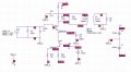
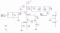
I am trying to simulate input stage of a variable gain preamplifier for acoustic hydrophone operating in frequency range of 90KHz to 110KHz. It is transistor based preamplifier. The gain of preamplifier is controlled through dc control voltage. I have attached the Orcad Capture Schematic snapshot.

The problem is that whatever dc control voltage (Vc) i set, output is still zero!

Any help in this regard is much appreciated.

Best regards
 

Attachments

crutschow

Joined Mar 14, 2008
38,423
Where is Vc?
Not clear how that circuit is supposed to vary the gain. :confused:

Below is the LTspice sim of an example circuit that does allow control of the stage gain:
It does that by bypassing the collector bias current for Q1 to vary its Gm without changing the collector bias voltage. since R1's current stays constant.

1745763411801.png
 

Thread Starter

naumankalia

Joined Feb 19, 2016
49
Where is Vc?
Not clear how that circuit is supposed to vary the gain. :confused:
Vc is simulated with DC supply connected with R05 resistor at base of Q04 transistor. The gain of Q01 based amplifier is varied by varying the current passing through collector of Q04 which in turn is controlled through Vc connected with base of Q04 through R05 resistor.
There is similar type of amplifier being explained at youtube " Design and testing of Voltage Controlled Variable Gain Amplifier, Smith Kerona"
 

crutschow

Joined Mar 14, 2008
38,423
The gain of Q01 based amplifier is varied by varying the current passing through collector of Q04 which in turn is controlled through Vc connected with base of Q04 through R05 resistor.
Okay.
That's how my circuit changes gain, but it doesn't vary the collector voltage as your circuit does.

Check the bias voltages on your circuit to determine why it's not working.
 

0ri0n

Joined Jan 7, 2025
167
Output is still zero whatever i set for Vc
Try some other, generic AF BJTs. Maybe there is some problem with the 2Nxxxx transistor models you seem to have imported.

As it's only 100kHz +/-10kHz, I used common, low frequency 2N3904 transistors. Overall gain is 25...0dB with a control voltage of 4...11V. See also the changes at the output transformer for a 50 Ohm output impedance.

Hydrophone_Var_Preamp_Schematic.png

Hydrophone_Var_Preamp_Gain.png
 

tonyStewart

Joined May 8, 2012
231
I suggest you choose an AM IF Radio design approach with passive BPF high gain then active BPF filter approach with detector and attenuator for AGC. Perhaps at least a 4th order BPF with 100 MHz GBW CMOS ICs for wideband high gain. The above design is a lost cause.
 

MisterBill2

Joined Jan 23, 2018
27,362
What I see is that the input protection diode is clamping the base voltage to the first transistor. There may be other problems, but that needs to be considered.
 
Top