KLH R6200 burnt up resistor

Thread Starter

Snayke62

Joined Feb 1, 2021
49
Take a close look at each electrolytic capacitor. Those are the large, black, cylindrical ones. ... not the small, ceramic ones. They are prone to failure when they age. It is difficult to tell visually if one of them is bad. The only sure way is desolder each one and test it. ... Any sign of leakage, maybe a discoloration next to the capacitor would be a clue, but the only sure way is to desolder and check.
Checking usually requires a capacitance measuring meter.
...
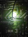
I have looked at those 100 times. They are not leaking or discolored at all. I have a meter with uF capacitor check. What should the reading be? And what exactly do the capacitors do? I mean I know they store energy. But let's say one fails in general, what are the symptoms? I can tell you that the main transistors all had 50 volts at the C pins. I used an IR temp gun all over the board for any hot spots. Nothing over 80 deg. But I also have to have a connection unplugged to get the unit to even stay on. So it wasn't trying to drive any output I'm sure. That's the only way I can bypass protection mode and keep the unit powered up.
 
Last edited:

drc_567

Joined Dec 29, 2008
1,156
... Different things can happen . Electrolytic capacitors sometimes are placed alongside voltage regulators to even out any ripple voltage following conversion from AC to DC in the bridge rectifier section. If the capacitor shorts out, then DC current goes directly to ground.
... If that has occurred in your circuit, then check a few of the capacitors around the voltage regulator part that looks burned.
 

Thread Starter

Snayke62

Joined Feb 1, 2021
49
... Different things can happen . Electrolytic capacitors sometimes are placed alongside voltage regulators to even out any ripple voltage following conversion from AC to DC in the bridge rectifier section. If the capacitor shorts out, then DC current goes directly to ground.
... If that has occurred in your circuit, then check a few of the capacitors around the voltage regulator part that looks burned.
There are small caps by the 2 voltage regulators. It's easy enough to desolder them and check. I guess I probably better.
 

drc_567

Joined Dec 29, 2008
1,156
... Note that all electrolytic capacitors are polarized, which means that they will have a distinguishing negative mark someplace on the case ... (-). This negative mark must always be installed with the same orientation that it had when it was removed. ... Make some kind of mark next to each capacitor before you remove it, something that can't be erased or smudged out. It might be a good idea to draw a sketch showing all the electrolytic capacitors and their polarity orientation, as well as capacitance.
 

SamR

Joined Mar 19, 2019
5,507
It was hard to tell from the pictures whether it was glare but I noticed some white discoloration that is indicative of liquid damage. Look the board over carefully and remove any "stains" with isopropyl alcohol, 70% or better without additives using a Qtip swab. Dust can be removed with a soft brush or DRY canned air. Also, look closely for any cracked solder joints and resolder if needed. Before removing anything, take pictures. Electrolytic caps are marked for Voltage, Capacitance, and Temperature. Replace with like-kind if needed.
 

Thread Starter

Snayke62

Joined Feb 1, 2021
49
It was hard to tell from the pictures whether it was glare but I noticed some white discoloration that is indicative of liquid damage. Look the board over carefully and remove any "stains" with isopropyl alcohol, 70% or better without additives using a Qtip swab. Dust can be removed with a soft brush or DRY canned air. Also, look closely for any cracked solder joints and resolder if needed. Before removing anything, take pictures. Electrolytic caps are marked for Voltage, Capacitance, and Temperature. Replace with like-kind if needed.
I marked the position. It reads 6349 uF. The cap says 6800. Good?
 

SamR

Joined Mar 19, 2019
5,507
OK, now we really need a circuit diagram. Because, for negative voltage smoothing the electrolytic plus IS on the relative ground rail! Put it back like it was or it will likely blow. The KEY is the stripe down the side of the can that indicates negative, not the base terminals. I am NOT an audio expert! There are different requirements for capacitors for noise suppression in audio systems that I do not know the requirements for.
 

Thread Starter

Snayke62

Joined Feb 1, 2021
49
OK, now we really need a circuit diagram. Because, for negative voltage smoothing the electrolytic plus IS on the relative ground rail! Put it back like it was or it will likely blow. The KEY is the stripe down the side of the can that indicates negative, not the base terminals. I am NOT an audio expert! There are different requirements for capacitors for noise suppression in audio systems that I do not know the requirements for.
The stripe goes down the side to the black terminal on both. It says negative. And the middle holes on the board are negative. For sure. The ground wire lead comes off it and goes to the chassis. And the resistor that was blown goes right to that same track as the capacitor terminal in question. That can't be right
 

Attachments

SamR

Joined Mar 19, 2019
5,507
Aha! Contact KLH for the circuit diagram. In the meantime, if possible, can you measure the voltage to see if it is + or - ? Time for me to go, getting late...
 

Thread Starter

Snayke62

Joined Feb 1, 2021
49
Aha! Contact KLH for the circuit diagram. In the meantime, if possible, can you measure the voltage to see if it is + or - ? Time for me to go, getting late...
I already did. It shows negative reading on ohm meter it I put positive lead on the negatives of caps. And it shows positive voltage . 2vdc if you put the leads on the correct polarity terminals . So it's not like they are charged backwards
 
Top