Just some general questions about remaking something from the past

Status
Not open for further replies.

Audioguru

Joined Dec 20, 2007
11,248
A tuner, MP3 player, phone or earphones outputs have "line level" signals that are about 2V p-p. Their output voltage and current cannot drive a speaker. The TDA7396 has a voltage gain of 20 times so its input volume control needs to be turned down a little when its input is line level for its output to be almost clipping. The almost clipping output levels from a modern ordinary car radio are about 22.4V p-p which is about 15 times too much to feed into a TDA7396.

The TDA7396 can make a louder output than a 44 years old car radio.
The output loudness of a TDA7396 with its supply boosted to 16V is not much more than a modern car radio.
 

Audioguru

Joined Dec 20, 2007
11,248
So in other words design, build and create an amplifier that doesn't amplify anything but headphones?
An audio power amplifier takes a line level low voltage and low current signal and amplifies it to a higher voltage and higher current signal.

They done it AG with components so why can't I ? they done it with 12V so why can't I ? and according to ohms law and that formula it will never be 23V peak to peak. 12V input- 1.4 = 10.6 and the formula only goes down from there.
You forget that a bridged output doubles the voltage and current for 3.5 times more power than a single amplifier.
A car battery is dead when it is only 12V, it charges at 14.4V. With a 14.4V supply, the bridged output of a TDA7396 is about 25.8V p-p which is 9.1V RMS which produces about 20W into 4 ohms just before clipping which is almost the same as a modern ordinary car radio.
You are boosting the supply a little to 16V so its output power will be a little more.
I think you want a lot more output power than a little more and another little more.
 

Thread Starter

Berzerker

Joined Jul 29, 2018
623
I'm trying to make sure I calculate my wattage correctly on a resistor. Second question is all my reading on it says to make sure you add in a (X) percentage over so it doesn't fail.
5V / 51 Kohm = .098 amps
5V X .098 = .490 watts
Hope I done it correct (?)
So 2, 3 or even 5 would be OK ?
 

MrChips

Joined Oct 2, 2009
35,017
I'm trying to make sure I calculate my wattage correctly on a resistor. Second question is all my reading on it says to make sure you add in a (X) percentage over so it doesn't fail.
5V / 51 Kohm = .098 amps
5V X .098 = .490 watts
Hope I done it correct (?)
You needed a calculator to do this, right? And still you are off by a factor of 1000.
Learn to do approximations by rounding off values. Then you can do this in your head.

51kΩ is close to 50kΩ

5V/50kΩ = 1/10 mA = 0.1mA
5V x 0.1mA = 0.5mW

You can also go directly in one step knowing the different formulas.

I = V / R
R = V / I
V = I x R

P = I x V
P = I x I x R
P = V x V / R

Thus,
P = 5V x 5V / 50kΩ = 5 x 1/10 mW= 0.5mW

For resistor wattage ratings, 50% or 100% over-rating is appropriate, i.e. multiply your calculated wattage by 1.5 or 2.

If you find the mathematics challenging, this chart may help you.


https://forum.allaboutcircuits.com/threads/resistor-wattage-help.133880/#post-1114963
 

Audioguru

Joined Dec 20, 2007
11,248
Nobody knows the voltage of pin 10 of the TDA7396 amplifier. It might be the entire 16V supply but I think it might be half at 8V. Then the power in the 51k resistor is (8V squared) / 51k ohms= 0.0013W, then any tiny resistor can be used.
 

Thread Starter

Berzerker

Joined Jul 29, 2018
623
.098 is only .002 from .1
.490 is only .010 from .5
Google said:
To determine the wattage, use a simple multiplication formula. The ampere (or amps) is the amount of electricity used. Voltage measures the force or pressure of the electricity. The number of watts is equal to amps multiplied by volts.
and I do mathematics just fine. It's the mohms, kohms and such I'm have to learn how to put in the calculator I use that my computer came with.
51 kohm = 51000 ohms
On top of that you have to learn about metal film, carbon, and wire wound resistors ?
Found a calculator
https://www.rapidtables.com/calc/electric/watt-volt-amp-calculator.html
No I don't know what voltage is on pin 10 but, there are only two voltages on the IC
5V and 12V. at 5V it gives .00049W, at 16V it gives .005W
Again your math messes me up.
8V squared (8 x 8 = 64) / 51 = 1.254
So no matter how you calculate it comes out to less than 1W. So a 2W or 3W would only dissipate more heat, last longer and cost only a few cents more right ?
 
Last edited:

ebeowulf17

Joined Aug 12, 2014
3,307
.098 is only .002 from .1
.490 is only .010 from .5

and I do mathematics just fine. It's the mohms, kohms and such I'm have to learn how to put in the calculator I use that my computer came with.
51 kohm = 51000 ohms
On top of that you have to learn about metal film, carbon, and wire wound resistors ?
Found a calculator
https://www.rapidtables.com/calc/electric/watt-volt-amp-calculator.html
No I don't know what voltage is on pin 10 but, there are only two voltages on the IC
5V and 12V. at 5V it gives .00049W, at 16V it gives .005W
Again your math messes me up.
8V squared (8 x 8 = 64) / 51 = 1.254
So no matter how you calculate it comes out to less than 1W. So a 2W or 3W would only dissipate more heat, last longer and cost only a few cents more right ?
You're off by 1000 again. Milliamp (mA) and milliwatt (mW) are 1000 times smaller than amp (A) and watt (W)

You're looking at fractions of a milliwatt, so you don't need 1W, much less 2 or 3. You only need 1/8th or 1/10th watt, whatever small size you find, and even then it's overkill. But if you want to use giant 3W parts, feel free.
 

ebeowulf17

Joined Aug 12, 2014
3,307
Or, to put it another way, you seem to be overlooking the difference between a 51 ohm resistor and a 51k (51,000 ohm) resistor.

If you would go through some tutorials, build really basic circuits on a breadboard (or in simulation,) like blinking LEDs, stuff like this would be second nature.
 

Thread Starter

Berzerker

Joined Jul 29, 2018
623
I have been ebeowulf, I'm just trying to get it in my head how to use the calculator to do it myself and no matter how I put it in the calculator I don't get the numbers AG posted. Got this page open now
https://www.electronics-tutorials.ws/resistor/res_7.html
And I did look at the page AG posted above.
No I don't want huge parts in it but I would rather be a little over than under. And yes AG I know it matters..:mad:
I took all day yesterday and didn't post not once trying to figure it out on my own. One way I would get this answer, then I would read more and get another. I'm confused...:(

I think I got it at 8V (8x8=64) / 51,000 = .00125 so AG rounded it off to .0013W
Mrchips said:
Thus,
P = 5V x 5V / 50kΩ = 5 x 1/10 mW= 0.5mW
so if I used the whole 16V (16x16=256) / 51,000 = .005W
Sorry MrChips I posted as I was quoting AG and it was you. This has been messing me up.
 
Last edited:

Audioguru

Joined Dec 20, 2007
11,248
Since the resistor heats with only a maximum of 5 thousandths of a Watt then use a 1/10W, 1/8W or a 1/4W resistor. A larger resistor will not dissipate more heat, it is able to dissipate more heat if the current in it is high enough. A 25W resistor will still heat with a maximum of only 0.005W as the 51k resistor in this circuit.
 

Thread Starter

Berzerker

Joined Jul 29, 2018
623
Thanks AG and ebeowulf. I'm still a little slow at calculating the watts but I'll get better. Only thing bad is I've done the patterns and components in Diptrace and will have to go back and look them up "with correct wattage" and create them all over again. Good practice in Diptrace though.
Another quick question about how much room to give a resistor away from the body for the bends in the wires if you use through hole ?
Is there like a rule of thumb that every one goes by ? I mean it's not like a capacitor with fixed lead width.
 

MrChips

Joined Oct 2, 2009
35,017
Thanks AG and ebeowulf. I'm still a little slow at calculating the watts but I'll get better. Only thing bad is I've done the patterns and components in Diptrace and will have to go back and look them up "with correct wattage" and create them all over again. Good practice in Diptrace though.
Another quick question about how much room to give a resistor away from the body for the bends in the wires if you use through hole ?
Is there like a rule of thumb that every one goes by ? I mean it's not like a capacitor with fixed lead width.
It's a matter of personal choice.
A general purpose PCB with thru-hole components will be happy with ¼W 5% resistors. Increase the wattage rating when necessary.
I layout components on a 0.1" grid.
Leads on ¼W resistors can be bent for 0.3, 0.4, 0.5" lead spacing, your choice. I use 0.4" spacing.
 

Thread Starter

Berzerker

Joined Jul 29, 2018
623
Thanks MrChips. going back through and re-doing my list on all of it and will start doing the patterns and component probably tomorrow.
 

Thread Starter

Berzerker

Joined Jul 29, 2018
623
Quick question on capacitors. In my reading it says the best capacitors for audio is polystyrene and polypropylene.
I'd rather spend a little more for better. should I use these types?
Edit: might want to change my mind those things are expensive.
OK second best for audio is?
 

MrChips

Joined Oct 2, 2009
35,017
Quick question on capacitors. In my reading it says the best capacitors for audio is polystyrene and polypropylene.
I'd rather spend a little more for better. should I use these types?
Depends.
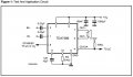
You have to show your circuit schematic and then we can advise on the best type of capacitor.
The capacitor used for coupling audio signal would be different from that used for power supply filtering.
 

Audioguru

Joined Dec 20, 2007
11,248
The 0.22uF input capacitors couple in the audio signal. I have always used Epcos poly-film capacitors for very low distortion. Polystyrene is very old and there are newer and better poly films (mylar and Epcos) It will be marked 220n. I have never used polypropylene.
The 10uF and 1000uF capacitors should be electrolytic. The 100nF capacitor should be ceramic to avoid high frequency oscillation.
 

Attachments

MrChips

Joined Oct 2, 2009
35,017
As I said, it depends on the specific application of the capacitor in the circuit. There is no one size fits all.

TDA7396.jpg

As the man says,

0.22μF are mylar or poly
100nF is ceramic disc
10μF is electrolytic
1000μF is aluminum electrolytic
 

Thread Starter

Berzerker

Joined Jul 29, 2018
623
Thanks MrChips and AG. I would have probably made a big mistake on all of them except the 1000uf, I had that one right and picked 25V for testing. going to order 25V and 50V just incase. one blows I got a better backup.
 
Status
Not open for further replies.
Top