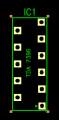
There's only one component in my PCB layout. I was still trying to see what gives with the hover over problem.
I know where my .dch file is but don't see where I can upload it.
Found it.
That's great, just upload the file with that one component. I was only going to look at that component anyway.
There should be an "upload a file" button near the box where you type comments and replies. You can also drag and drop files from your folders into the reply window.
This file type might not be accepted on this forum website (some types are forbidden as an attempt to improve security.) If it won't accept the schematic and board files directly, compress them into a .zip file and upload the .zip file. It definitely accepts those.
Good news, bad news. The good news is that it looks fine on my end (older version of DipTrace, V 2.4.0.2)
The bad news is that I don't know why it would appear the way you've described on your end, especially if other components show up normally. If everything was acting funny, I'd say you had some different graphic or view settings, or simply had some layers hidden, but if other components appear normally and only yours misbehaves, I'm at a loss.
You might get better support on the DipTrace forums, where there is a lot more expertise specific to DipTrace. I've had good experiences with it over the last few years, but I don't use it on a daily basis, and I'm certainly not an expert!
And the schematic? am I doing it right so far?
I'm looking into the layers thing now and if I click on it in the layers panel they show up but only till I hover over it again then they disappear again
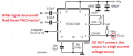
If you put +5V on the clipper pin #4 then if there ever is an error then the transistor on pin #4 will try to drive the +5V to ground which will cause the transistor to die. The datasheet does not say its maximum allowed current which must be very low since they show it with 10k and 15k
series resistors to drive the high input resistance of a uC.
If you put +5V on the clipper pin #4 then if there ever is an error then the transistor on pin #4 will try to drive the +5V to ground which will cause the transistor to die. The datasheet does not say its maximum allowed current which must be very low since they show it with 10k and 15k
series resistors to drive the high input resistance of a uC.
English please AG. It would be like you asking me the difference in diametral pitch gear cutters and what number to use to cut what number of teeth on a gear.
shortbus said:
Like I said I didn't look at the component. And Ebeowulf addressed the SIP and DIP question.
Those are the inputs from the radio is what I thought AG. Tell if I'm wrong(?) So nothing goes to pin #4 (?)
And I just learned a valuable lesson "DO NOT" hit the convert to PCB unless your absolutely sure you have everything right. Now it locked me out of that PCB file name and I don't know how to undo it. and the stand-by can I leave it open "nothing hooked to it"
Edit; You said high voltage so I do put current to it (?) the 1.5V (?)
post #344 I uploaded a schematic file AG but those are generic components "ones I just picked from the list randomly" and not the actual ones. Not sure if I should do it that way or is it OK for a schematic layout ?
The TDA7396 and all other IC amplifiers have voltage gain so that line level signals from a tuner, MP3 player, phone or earphones output can drive the inputs. A car radio output has such a high level that it might damage the input transistors in the IC but ST Micro does not say the maximum allowed input.
The voltage gain of the TDA7396 is 26dB which is 20 times so you must attenuate a car radio output to 1/20th. Are you making two of these amplifiers for stereo?
Pin 4 and its 10k pullup resistor is an output to drive a uC or opamp to warn that clipping or a problem is occurring. They say the clipping warning signal can drive a gain compression circuit to reduce overdrive.
The schematic files in post #344 are for your pcb software that I do not have.
Yes one pair if that's what your asking, right and left. but the input voltage would still be the same on both sides right?
So I would have to add a step down audio transformer is what your saying ?
Two resistors in series make an attenuator. If each radio output channel is bridged then you need 4 resistors to attenuate each half of the bridged output of each channel. Then the output from your amplifier will be almost the same level as from the car radio so you have gained almost nothing. Double the power sounds only a little louder. Your TDA7396 amplifiers and supply voltage boosters are not doubling the power.
If you use the TDA7396 amplifiers with voltage boosters for a 16V supply then use 2 ohm speakers (very expensive) or two 4 ohm speakers in parallel for each channel. Then the power will be a little more than doubled and will be noticeably a little louder than the original car radio.
Maybe the original car radio can drive its own 4 ohm speakers and drive your TDA7396 amplifiers with voltage boosters and two paralleled 4 ohm speakers per amplifier. Then the result will be a little louder than a little louder.
Still trying to find out more on the TDA7396. How much input volts it can take on the inputs from the radio. The datasheet says the outputs are rail to rail and no need to bootstrap capacitors if that means the same thing (?). Says it can drive loads as high as 2ohm.
Still trying to find out more on the TDA7396. How much input volts it can take on the inputs from the radio. The datasheet says the outputs are rail to rail and no need to bootstrap capacitors if that means the same thing (?). Says it can drive loads as high as 2ohm.
Since its gain is 20 times and with your 16V boosted supply then its input is about 1.5V peak-to-peak when its output begins clipping and sounding awful. The car radio maximum output is about 23V peak-to-peak. Since nobody plays an amplifier that has horrible clipping then they do not say a maximum allowed input voltage. You should attenuate the car radio outputs down to headphones level.
When the TDA7396 drives a 2 ohm load then its output power is not doubled, it is 1.6 times the 4 ohms power but the heating is almost doubled.
Simple arithmetic shows that its outputs are not rail-to-rail.
So they can make a radio with all the other stuff in it plus an amplifier built in but if I try to just make an amplifier by itself it will never work ?
they can get all that power out of it but because its me it will never get anywhere close ?
Is that about right?
They done it AG with components so why can't I ? they done it with 12V so why can't I ? and according to ohms law and that formula it will never be 23V peak to peak. 12V input- 1.4 = 10.6 and the formula only goes down from there.

 Facebook
 Google
 GitHub
 Linkedin