Because you have no education or experience with electronics then unfortunately everything you do, say and find are WRONG:
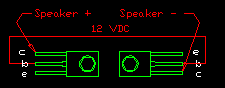
1) The video shows a little BC547 NPN transistor. It has the European small low power transistors pins layout as CBE on its datasheet . American little transistors have pins that are EBC. But the POWER Darlington transistors are completely different because their collector gets hot and is the rear metal that is bolted to a heatsink and is also the middle pin.
2) We don't call the positive supply wire "hot".
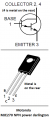
3) What is the part number of the NPN darlington transistors that you sketch with an antique case? They might be European with a different than American pins layout. Oriental transistors use another pins layout. Motorola used to use that old case and I found this one but its max current is too low:
Depends what voltages you have on the emitter and collector. You must avoid exceeding the reverse breakdown voltages of the junctions or the forward current rating.
But the POWER Darlington transistors are completely different because their collector gets hot and is the rear metal that is bolted to a heatsink and is also the middle pin.
I don't think this is the case, If so the 12VDC would not be going to the middle pin.
I do think now it's a NPN. What I said about having NO electrical experience might be a little wrong. I have done wiring in my time, relays , timers, control panels....etc. But it's mostly been AC. I've done programming and just plan 110AC, 220VAC and 440VAC when I would install the machines the company built. But no electronic board design. I have known for many years what capacitors, diodes and resistors are but never took the time to know how they worked. I would have a schematic and would just wire it to what it said to.
Audioguru said:
What is the part number of the NPN darlington transistors
I don't know "yet". The numbers are worn off of it and I'm having to do some more reading on it to find the one that will work. I will try to reframe from using the word research from now on. And I will not use "hot" anymore. I get that someone looking on here would say that's wrong.
If your referring to my drawing and the font, we don't call them sketches and it's from my reference drawings. it's and old design practice used to keep you from going back and forth incase you forgot a measurement. and the font is autocad standard. See I'm an old man but, this dog is just trying to learn a new trick. My "sketch" should have looked like this:
to be correct.
I have also found that it uses only what I can describe as a floating ground.
If your referring to my drawing and the font, we don't call them sketches and it's from my reference drawings. it's and old design practice used to keep you from going back and forth incase you forgot a measurement. and the font is autocad standard. See I'm an old man but, this dog is just trying to learn a new trick
Then you should also learn that in electronics you don't use true representations of a device(your drawing). Schematics use a "idealized"(don't know the real term) depiction of the devise. To use drawings like you show, a schematic would be so big it would not be practical.
Then you should also learn that in electronics you don't use true representations of a device(your drawing). Schematics use a "idealized"(don't know the real term) depiction of the devise. To use drawings like you show, a schematic would be so big it would not be practical.
Yea but I'm only on my fifth day at it and it's my only way "at the moment" that I can relay to you what I have. Mechanical was my thing and I am looking into how to do the symbols in autocad. been a little more involved in reading about what I need and which one will work. I think there's a symbol library I need to download.
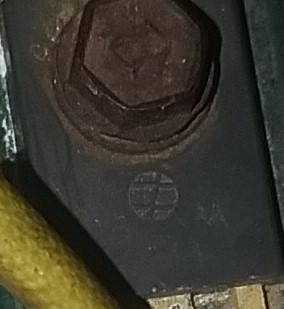
Digikey is great. talk to rep there and he's helping out a bunch. Got another question in a pic I took with my phone I could make out an big M on the transistor. Does this stand for Motorola?
I'm beginning to get crushed. the capacitors were made by a company called Rochester Medical company or cooperation which is still in business but just guessing they would be more than what the original whole MindBlower would cost by themselves. anyway the spec was a 1uf +60-20 15v.
Yea but I'm only on my fifth day at it and it's my only way "at the moment" that I can relay to you what I have. Mechanical was my thing and I am looking into how to do the symbols in autocad. been a little more involved in reading about what I need and which one will work. I think there's a symbol library I need to download.
I too came into electronics from a mechanical back round(die making), at a later stage of life. And wish I had found this site earlier, as bad as you think it is here, it is nothing compared to some of the sites that have gone under. They were brutal to newbies.
If you know Autocad or any other drawing program you also have a leg up on where I started. No Cad experience at all. That said, why not go into a regular schematic program, one made to do it, not as an add on? i found, because I have no Cad at all that Diptrace is about the best and easiest to learn, but that's just me. Others here like some of the more complex programs, but they all get you to the same place. The good thing about the electronics programs is once you draw a schematic you can convert it into a printed circuit board from there all in one package. I'll give the link to Diptrace but I'm sure others will give one to their favorites. https://diptrace.com/download/download-diptrace/
There are also some tutorials online to help you if you Google them.
Thank you shortbus. I did download Autodesk Eagle and It's a schematic, PCB design software. I will download diptrace also. Never know it might be easier to learn (?) I've only given up on the original version of the Mindblower "YES Audioguru you were right, it's not worth the effort to hunt down all those obsolete parts". Found a 50 watt project on line that I think would suit me to get started with. http://yarbnas.com/video/how-to-make-12v-amplifier-used-3-transistors-d718-and-b688-and-2n3904-50w/
If not there are those kits you buy. Just something to get my feet wet in electronics. And shortbus I have been a machinist all my life and loved it. My Dad turned me on to it when I was young. I've done a little die making but mostly made the parts for the Machines we built. Later I got into Cad and they move into drafting. Now I'm no engineer or master at it and will never claim to be but, I can get around in it pretty good. I hope you guys will help me in the future.
Oh and what are those square boards called that I see people on the video's using to just stick there components in where it has the wiring underneath? It's like a test board I guess.
Thank you shortbus. I did download Autodesk Eagle and It's a schematic, PCB design software. I will download diptrace also. Never know it might be easier to learn (?) I've only given up on the original version of the Mindblower "YES Audioguru you were right, it's not worth the effort to hunt down all those obsolete parts". Found a 50 watt project on line that I think would suit me to get started with. http://yarbnas.com/video/how-to-make-12v-amplifier-used-3-transistors-d718-and-b688-and-2n3904-50w/
If not there are those kits you buy. Just something to get my feet wet in electronics. And shortbus I have been a machinist all my life and loved it. My Dad turned me on to it when I was young. I've done a little die making but mostly made the parts for the Machines we built. Later I got into Cad and they move into drafting. Now I'm no engineer or master at it and will never claim to be but, I can get around in it pretty good. I hope you guys will help me in the future.
Oh and what are those square boards called that I see people on the video's using to just stick there components in where it has the wiring underneath? It's like a test board I guess.
The little rectangular boards with rows of holes are called breadboards. They're incredible useful for experimenting and prototyping certain concepts, but they also have many limits. They're well suited to low-ish voltages, low currents, and "low" frequencies, which in the electronics world ends up meaning totally fine for audio, but no good for radio frequencies.
Also, plus 1 for DipTrace. I've done plenty of drafting in AutoCAD, TurboCAD, Inventor, and ProE, so I'm not scared of advanced software packages, but I personally think the Eagle interface is just awful no matter how you slice it. I'm amazed so many people like it. I think DipTrace is so much better. Still, just personal preference.
Downloaded Diptrace yesterday first look at it an I could tell this might be the one I should learn. But was a little down on my Mindblower first try effort so I went an grabbed a few beers and pondered over it. Now I haven't gave up on this "per-se". It will just never be an original which is what I was wanting. they don't make 15VDC capacitors anymore from what I can find or there not readily available. One of the items after just sitting there came to me as being a voltage regulator on the transistors cos the way it hooked to the transistors is only on the collector side. I could just find Higher voltage parts and just use a converter as Audioguru and I were talking about. Let's say 35VDC or 50VDC right? Purchase parts for this voltage and work from there yes? Maybe a Mindblower 2.0 thing just saying.
Now I'm opening Diptrace to give it a shot and see if can figure it out.
Edit: I'll be purchasing a breadboard and some parts in the next few days to get me started. got know what I need first.
Those 15V caps were never all that popular. And the cap voltage value should always be at least 1.5 times the working voltage of the circuit, higher in most cases won't hurt you. And since you were a machinist, which is what I started out being before going into die/mold making, one thing you will have to forget is measurement accuracy when it comes to electronics. I like you was always striving to make things exact and to a print. Electronics isn't anything like that. That last sentence may get a lot of push back but it is the truth.
When you get farther into this, you need to download data sheets for the components you think will work for you. Those data sheets will tell you a lot about the component. And never use the value called something like "typical value", that will get you in trouble down the line. Always design for the worse case scenario, and use the low value as a design point. Many of the normally used components won't last long when used at the voltages listed in the "headlines" of a data sheet. This is because of manufacturing tolerances, it isn't like machining where things can be done to pretty exact tolerances.
And to your choice of schematic programs, if you can make Eagle work for you that's fine. But like ebeowulf17 said, it is just to much harder to use. But many people here and other places love it. Electronics is too hard on it's own without making it harder.
Was it the sound or the look of that product you were after? I just the look, why not just make the enclosure look like it is retro? Retro with improved electronics.
No it wasn't the sound so much. I also was pondering over the distortion part of it and will probably ask in the future what will fix this "something like a chip or component that will lower it. The Mindblower was like one of them things like the old Quake II game to me. Now kids play things like GTA 5 which I like too but, I think it's more of a nostalgia thing. I remember getting my first set hooking them up and just listened in total amazement. No they don't have to be exact, just something to hold in my hand and say "I done this". They could be like 100, 150, 200, 300 watts per speaker if possible and It can have more components in it. The original I got of the aluminum heat plate was only 3" X 4.1/4" . It would have to be bigger already to fit a new model speaker anyway, so my PCB could now hold more which the board looked quite small on anyway (Only seven parts) two of which weren't on the board but bolted to the heat plate. Another question: The transistors if purchased with the right specs can essentially put out more watts yes? and reading up some more on it I typed in 12VDC voltage regulator and it pulled up a pic of what still looked like a transistor to me.... are they one and the same or do they work different internally.
In Diptrace can I take the top and bottom silk, copper pours..etc. like layers in a cad program? Only the silk is like the coating on top and bottom and copper pour and the others are layers are in between them? can you make your copper pour as thick as you want? or is it best to just go by the standards? How many layers are usually in a PCB? Can you put different types of silk on the top and bottom? for instance if you want all your solders to be on top and not bottom. just fooling around in it. I found out I don't like the video tuts with the stupid music playing in the background already. It's like going to school and the teacher walk in turn on some music and just start pointing at things with no explanation of why you do this.
Copper pour is not pouring real copper. You are only creating an optical mask that defines what area will not be etched. The thickness of the copper pour area will be determined by the original thickness of the copper laminate that you specify, such as 1oz, 2oz, etc., when you ask the PCB shop to fabricate your board.

 Facebook
 Google
 GitHub
 Linkedin