Just some general questions about remaking something from the past

Status
Not open for further replies.

Thread Starter

Berzerker

Joined Jul 29, 2018
623
That's what I want. looking up them now but I figured it out last night.
THANK YOU! I had to remove it from the board and thought it was a three wire transformer, come to find out it had four. Still don't know what the output is?
found a local electronic store think I will take them by and just see what they say.
Got the number from one of the capacitors but I can't seem to pull it up by the numbers.
 

Audioguru

Joined Dec 20, 2007
11,248
Most transformers have four wires, two for the primary winding (input from the amplifier) and the other two for the secondary (output) winding.
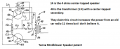
I found the patent of the Tenna Mindblower speaker and it shows a 5 wires input transformer with its center-tapped secondary feeding two darlington emitter-followers which drive the 4 ohms center-tapped speaker. So it has a custom-made transformer and custom made speaker.
 

Attachments

Audioguru

Joined Dec 20, 2007
11,248
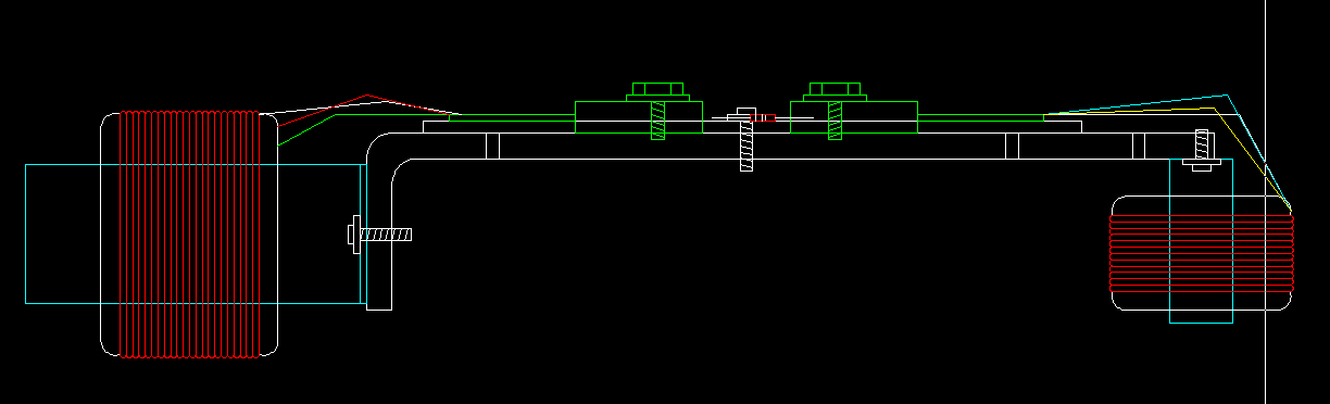
The transformer 48 on the patent has 2 wires on its input (right side) and 3 wires on its output (left side) that feeds the Darlington transistors. Then it has 5 wires. The custom-made speaker 41 has 3 wires.
 

Attachments

Thread Starter

Berzerker

Joined Jul 29, 2018
623
I know our problem now you pulled up a spec from the old design. Now there are two transformers on them.
one for changing it from a three wire speaker to a two wire speaker and the other I don't really know what it does, But it's bigger fits on the opposite side and hooks between the transistors and a few other things.
Again thank you for helping me!
So if I were to google what would I be looking at a five wire 14-48 transformer coil
 
Last edited:

Audioguru

Joined Dec 20, 2007
11,248
I have not found a schematic of the MindBlower speaker with the new design that added an ouput transformer to convert the custom 3 wires speaker so an ordinary common 2 wires speaker can be used. This transformer is not common today and also must be custom designed and made. You can decide to use an expensive design with good deep bass and sizzling highs or a cheap design that sounds like a cheap little old AM radio.

You cannot simply use Google to find a suitable 5-wires transformer and 3-wires to two-wires converter transformer. There are no such things available today, these things are 40 years old. They must be designed properly to match the Darlington transistors and the raw speakers including all the audio spec's you want.
 

MisterBill2

Joined Jan 23, 2018
27,833
All cheap factory installed car radios are inexpensive and are bridged. A bridged car amplifier produces 15W into a 4 ohm speaker with low distortion or 30W with horrible distortion. Tenna listed the power of the mindblower speakers at 60W with no mention of distortion and maybe 2 speakers at 30W each.

Half-decent car radio systems already have 6" x 9" coaxial speakers with proper crossover parts already installed on the rear shelf so the boxes are used only in pickup trucks. The front doors have 6.5" coaxial speakers installed in them. Many cars have two tweeters on the front dashboard.
12 years ago I had a Chevrolet that used 2 ohm speakers with bridged amplifiers that produced 28W at low distortion per channel or 56W per channel with horrible distortion. It had an inexpensive Pioneer 10" sub-woofer driven with its own amplifier/power supply to 100W.

You talk about car amplifiers that cost $300 to $500 . A TDA7377 (European) bridged stereo car amplifier costs only $1.55 each today at Newark in the US but they are not made anymore because Chinese ones are cheaper.

There is a whole lot more to an amplifier than just the power IC. Even the layout of that simple circuit on the board is critical to avoid feedback and instability. Power supply and heat sinking add a whole lot to both cost and complexity.The problem with anything that you buy today is that it is designed with minimum cost as the primary requirement, and minimum size second. This means very high power density, highly stressed parts, and so compact that it is not repairable, usually.
Besides all that, though ANYBODY can throw a check and get something that works, sort of, for a while, and what does that show besides that they can pay somebody else to do it for them?
 

MisterBill2

Joined Jan 23, 2018
27,833
I have not found a schematic of the MindBlower speaker with the new design that added an ouput transformer to convert the custom 3 wires speaker so an ordinary common 2 wires speaker can be used. This transformer is not common today and also must be custom designed and made. You can decide to use an expensive design with good deep bass and sizzling highs or a cheap design that sounds like a cheap little old AM radio.

You cannot simply use Google to find a suitable 5-wires transformer and 3-wires to two-wires converter transformer. There are no such things available today, these things are 40 years old. They must be designed properly to match the Darlington transistors and the raw speakers including all the audio spec's you want.
Push-pull output transformers are available and it is common to pick the operating points to use a transformer that is available. But don't even consider google for a search thing because it is a poor choice on electronic stuff.
 

Thread Starter

Berzerker

Joined Jul 29, 2018
623
Yea I found digikey yesterday. And you all knowing I said I know nothing about electronics I spent a lot of my time lately on tutorials on electric symbols, learning color codes, the difference in resistors and such. And yes MisterBill2 I know they were cheaply built but that was the whole idea back then. this was when the amplifier craze was just getting in gear. I remember going to the stereo shop and saying I can't afford that!
Then someone told me about a new company in Montgomery that just opened up. Went there and bought my first set for I think around $50.00 speakers included. this was the old design that Audioguru and Me have been talking about. After about a year or two they blew up and went back and they had upgraded to the new design. I've owned about five sets of these and wish I would have never threw the others in the garbage. And a note to Audioguru I even downloaded Autodesk Eagle yesterday just to learn PCB design. When I set my mind to something I go all in. I have the PCB layout and I'm sure they made that way for a reason and with a lot of time and whole lot of luck I will at least finish the
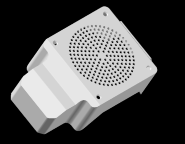
the designs and layouts. They got so hot you couldn't touch them and often blew fuses and I wondered why they done that sooo, I designed a cover that incorporate a computer fan to keep them cool. Now I don't know if they will get so hot that it will destroy the fan but that's what research and development are all about right? So give me an opinion on it, what do you think?

I did say I had Mechanical experience! most of my life I built, designed and installed sawmill equipment. But I always had an electrician to do the wiring so I never got into it.
 
Last edited:

Audioguru

Joined Dec 20, 2007
11,248
Push-pull output transformers were used on all audio amplifiers 60 years ago because they matched the high voltage, high impedance vacuum tubes to the low impedance speaker and old guitar amplifiers use them today. The MindBlower speaker does not use a high voltage and vacuum tubes so these old transformers cannot be used. Since output transformers are not used with transistors then a suitable transformer must be custom designed and manufactured at a very high cost.
 

Thread Starter

Berzerker

Joined Jul 29, 2018
623
First I'm trying to get the specs for it. So I think it's a little early to say I can't find one. If I run into that problem then I will just redesign it with something that's modern. I would love to do an original but will settle for what I can make money off of. The name itself if placed on the market would generate a lot of attention.
 

shortbus

Joined Sep 30, 2009
10,049
I would love to do an original but will settle for what I can make money off of. The name itself if placed on the market would generate a lot of attention.
If that was the case, don't you think Tenna would still be making, selling them? If not Tenna itself there would be a company that bought the rights to the design. The real way to look at something like this is the way they are making "retro" stereos today, putting a new design amp/receiver into an old design "box".
 

Thread Starter

Berzerker

Joined Jul 29, 2018
623
This is only my third day on this project and I know what I posted above is not what would go in it.
but I know there IS something out there similar to it that could be mounted on the circuit board and do the job. Too many video's of do it yourself out there were you can make X watt amplifiers. With parts lists included.
 

Audioguru

Joined Dec 20, 2007
11,248
The cheap tiny transformer you found on Digikey is used in a SMPS (Switched Mode Power Supply) and does not pass wideband audio, it passes only 300kHz high frequency radio waves.

Anybody can make a high power audio amplifier without any transformers if they have a supply voltage that is high enough.
Your truck has a voltage that is 14.4V when the battery is charging. Then a transistor amplifier can produce a maximum output of about 11.4V peak-to-peak which is 4V RMS. Then the output power with very small clipping is (4V squared)/8 ohms= 2W which in not much. Use a bridged transistor amplifier then the output power is 7W which is still not much. Use a bridged transistor amplifier with a 4 ohm speaker and the power is almost 14W. Use a SMPS power supply to step up the 14.4V to 100V with a high power audio amplifier and the power will blow your head off.

Many amplifier spec fake amounts of power with very high distortion so that the power number is higher. Most ordinary car radios advertise 25W per channel at high distortion or 14W with low distortion.
 

Thread Starter

Berzerker

Joined Jul 29, 2018
623
I think the big transformer only turns the input from 12 volts dc to 24 volts dc and this can be done with these three parts.
1. (3) 16v 10 uf
2. (1) ic LM7824
3. (1) capacitor 104J 100v
added to the board. I can't test this at the moment as my meter battery died.
Why don't the make DC to DC Transformer? been looking like crazy.
Or do they and I just haven't found them
 
Status
Not open for further replies.
Top