Just some general questions about remaking something from the past

Status
Not open for further replies.

Audioguru

Joined Dec 20, 2007
11,248
I think the big transformer only turns the input from 12 volts dc to 24 volts dc and this can be done with these three parts.
1. (3) 16v 10 uf
2. (1) ic LM7824
3. (1) capacitor 104J 100v
added to the board. I can't test this at the moment as my meter battery died.
Why don't the make DC to DC Transformer? been looking like crazy.
Or do they and I just haven't found them
You don't know the basics of electronics and you want to make and sell custom-made speakers?
A transformer works with AC only and makes lots of smoke with DC.
A 7824 has an input from 26VDC up to its maximum and provides a regulated 24VDC output. It does nothing when its input is less than 25VDC.

You need a powerful SMPS with a little high frequency transformer in it to stepup the DC voltage. Then you need an amplifier that works from that boosted DC voltage. Then you need raw speakers that survive the extra power.
 

Thread Starter

Berzerker

Joined Jul 29, 2018
623
Audioguru said:
A transformer (using the term in its traditional sense) works with AC only.
I am learning! Now if I could just find a miniature version of one, Those are a little big for what I need. also trying to figure out how to search a part on digikey. Put in my part number and what came up wasn't what I put in.
Edit: How do you find out the side of a part on a data sheet for drawing purposes
 

Audioguru

Joined Dec 20, 2007
11,248
A miniature audio transformer provides no low bass frequencies and not much output power.
Most datasheets (except Chinese ones) show the dimensions of the device.
 

Thread Starter

Berzerker

Joined Jul 29, 2018
623
Audioguru said:
A miniature audio transformer provides no low bass frequencies and not much output power.
Sorry I was talking about the DC converter.
Audioguru said:
Most datasheets (except Chinese ones) show the dimensions of the device.
I'm still looking for it, It's on the pic as the (L) dimension but there's no (L) on the Data sheet.
 

Thread Starter

Berzerker

Joined Jul 29, 2018
623
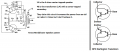
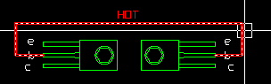
OK I no longer think it's a converter "the bigger one the left side of my drawing" After looking at the PCB and what components it was hooked to I think it has something to do with the output to the speakers. The resistors are PNP type and hot is hooked to the base of the resistor and the leads off of it circle between them and straight to the speakers.
 

Thread Starter

Berzerker

Joined Jul 29, 2018
623
OK I gotta know what I'm doing wrong! The little capacitor has writing on it. one side has either ZSF or Z5F and on the other it has RMC 150 200 or RMC 150 20o. No matter what I type in search or on digikey it pulls up the round ones not the thin, flat orange type
 

Audioguru

Joined Dec 20, 2007
11,248
The patent shows NPN Darlington transistors and no capacitor. The transformer feeding the 2-wires speaker must handle high power so it must be larger than the low power transformer at the input of a newer MindBlower speaker.
 

Thread Starter

Berzerker

Joined Jul 29, 2018
623
The tuts I read said if you put the black lead to the base and the red lead to emitter or collector and you get a reading it's a PNP.
But I thought this sounded funny cos the 12 volt power goes straight into the base on the transistor. When I do place the meter on it with black on the base and the red on either of the others I get a reading of 632 on the 2000k setting. The other way I get nothing.
 

Thread Starter

Berzerker

Joined Jul 29, 2018
623
Bad thing is all that time I spent going by the original measurements and drawing out the fan, making sure it fit and had room, the cover and all that was for nothing. The speakers nowadays have bigger, stronger magnets on them. So I'm having to do some redesigning.
 

Thread Starter

Berzerker

Joined Jul 29, 2018
623
OK Audioguru now I know you probably know your stuff BUT!, I'm beginning to think your running me around in circles.
The Darlington transistor thing. I'll show you what I found:
[URL said:
https://www.electronics-tutorials.ws/transistor/darlington-transistor.html][/URL]
The Darlington Transistor named after its inventor, Sidney Darlington is a special arrangement of two standard NPN or PNP bipolar junction transistors (BJT) connected together. The Emitter of one transistor is connected to the Base of the other to produce a more sensitive transistor with a much larger current gain being useful in applications where current amplification or switching is required.

Darlington Transistor pairs can be made from two individually connected bipolar transistors or a one single device commercially made in a single package with the standard: Base, Emitter and Collector connecting leads and are available in a wide variety of case styles and voltage (and current) ratings in both NPN and PNP versions.
Yes you can buy Darlington Transistors:
https://www.mouser.com/Semiconducto...MIhtOVqfrL3AIVGXZeCh1U4wqEEAAYASAAEgJKjfD_BwE
I thought this was a help forum?
You post a pic of a Tenna transformer give no reference to it's location, Tell me the patent says Darlington Transistor, Still no references.
That pic for what I'm seeing only shows the transformer and the speaker output wires and the leads coming off the board to it! All it has is a bunch of numbers to it which look like the coil to the speaker. As I said YES I'm new to electronics but I'm not a total idiot to them. I built my own M.A.M.E arcade cabinet years ago and I Have fixed computers on the side for years. From your first post to me it's been nothing but negativity and never answering the questions I have asked. Can't be done, It will cost to much and so forth. It sounds like you don't want anyone to succeed at anything. If you want to help, HELP if you don't, DON"T! but I'm spending my time trying to research and to get the answers I need so if you have info where it shows and says it's a Darlington Transistor and not who came up with the idea of how to use one as a switch "show me" Cos if you that Info you must be looking at a schematic of it to which so far as I know there are none.
Edit: From what I can tell I'm the only person that has a wiring diagram and an old pair from which I can get info.
 

shortbus

Joined Sep 30, 2009
10,049
I thought this was a help forum?
Edit: From what I can tell I'm the only person that has a wiring diagram and an old pair from which I can get info.
It is a help forum. But from the start you have been combative. The help your getting is -
1. don't waste your time and money if you think this will be a "money making proposition".
2. don't you think if there was still a market for this product there would be someone making them?
 

MrChips

Joined Oct 2, 2009
35,017
Let me get this straight.
  • By your own admission, you know nothing about electronics.
  • You take a century-old design and want to reverse engineer it.
  • In today's dollars, the unit sold for $200 (my guess).
  • You want to recreate the design with components no longer available.
  • A modern design with modern components is sold on the market for under $5.
  • You have no idea if there is a market for your idea.
  • You hope to make a few $million on this.
Good luck on your endeavor.
 

Audioguru

Joined Dec 20, 2007
11,248
Berserker, you know nothing about electronics.
You are completely wrong about the NPN type of darlington transistors shown on the MindBlower patent, also wrong about which pin is which and that of course Darlington transistors are still made and used. Simply look on a datasheet of a powerful Darlington transistor to see the type and see the pins
But you must engineer the required maximum voltage, maximum current, maximum heat dissipation and frequency of the Darlington transistors used in this antique design.

Here is the patent showing NPN darlington transistors and NPN Darlington transistors shown in Google that shows that you are WRONG about NPN or PNP and also wrong about their pins:
 

Attachments

Thread Starter

Berzerker

Joined Jul 29, 2018
623
Me said:
Your telling me about watts and stuff, that's not what is important to me. I already said I know nothing about electronic design. Like the comment about the transformer! I'm sure there is an updated version to this. I was wanting to find out about what I needed to find out what they were.
Your only telling me I shouldn't do it right? what would happen if came back here and posted I just made a quarter million this year would you say I was wrong then? Just need some help on what to do.
If it's my punctuation your referring to is the exclamation marks, google it , it can also be used to show emphasis and not just hollering. If you all took them that way then I apologize.
There are a few other examples of this and I will not quote them all but the fact does remain that some of the questions I asked were over looked and something else posted not the answer to the question I asked. If I were on a forum and knew what you guys know any question someone asked me I would just answer it. Think of what I'm trying to do as if someone found an old car and wanted to restore it I'm sure they already know they will be spending a lot of money and time. that's not the point.. They might run into a problem painting the car "If they never painted before" so they would ask for tips.
 

Thread Starter

Berzerker

Joined Jul 29, 2018
623
Can I still just have a question answered?
Can you put 12volts DC on the base of a PNP Transistor. from all my test it still comes up PNP.
 

Audioguru

Joined Dec 20, 2007
11,248
Can I still just have a question answered?
Can you put 12volts DC on the base of a PNP Transistor. from all my test it still comes up PNP.
Why put +12VDC on the base of a PNP transistor?? Usually the emitter connects to +12V and the collector has a load resistor to 0V and the base is biased at a diode voltage drop below the emitter voltage. You could also make the PNP an emitter follower with the collector at 0V and the load resistor from +12V to the emitter then the base voltage is a diode voltage drop below the emitter voltage. Darlingtons have two diode voltage drops.

The NPN darlingtons in the MindBlower patent are emitter-followers. The bases are fed from the outputs of the transformer on the right (which is fed #50 from the output of a car radio). The collectors of the NPN darlingtons connect to +12V. The emitters connect to the speaker voice coil #14.

Oh, are you still testing unmarked darlingtons that have their part numbers missing? For an NPN darlington, when the base is Positive and the collector or emitter are Negative during a diode test then the junction conducts. On a diode test a multimeter will show a voltage of about 0.6V when the junction on a silicon transistor conducts and open, infinity or error when the polarity is reversed.

"The tuts I read said if you put the black lead to the base and the red lead to emitter or collector and you get a reading it's a PNP."
Correct because the black meter lead on the base (the N) is negative, not positive.

"But I thought this sounded funny cos the 12 volt power goes straight into the base on the transistor."
No, the +12V is shown connected to the collectors of the NPN darlingtons, not the bases. The bases are shown connected to the outputs of the transformer on the right.
The datasheet for the Darlington transistor will show which pin is which. The metal tab on the case and the middle pin are usually the collector with the same connection. But maybe your antique darlingtons do not have the modern epoxy case with a metal tab.
 

Thread Starter

Berzerker

Joined Jul 29, 2018
623
Thank You Audioguru. I have found three out of the seven original parts and yes there in stock and this is one I'm still trying to determine which one to buy.
 

Thread Starter

Berzerker

Joined Jul 29, 2018
623
here's where I'm having the problem with what you tell me.
when tested as said with it off the board I get PNP. and I agree why would you put a hot wire on the base of a transistor.

this is where the hot leads go.
Or do I have the emitter and collector backwards?
 
Status
Not open for further replies.
Top