
I'm trying to simulate a circuit using IR2110 as the gate driver to build a medium power DC converter.
While running the simulation with the given schematics, I get an error on the HO side. The HO waveforms a square wave varying between 40 - 0V, even when the VCC is set at 15V.
When I remove the connection of the HO to the gate of the high side mosfet, the waveform varies between 15v-0v - as it should.
I have also checked the voltage between Vb-Vs and it is almost at a constant 15V.
I have varied the values of the Bootstrap capacitances, the gate resistance and the resistances between gate and source but the issue continues,
At this stage, when I check the value across Vs, I get the expected waveform with values fluctuating between 24V - 0V.
However when I introduce an ideal NMOS with the LT spice components, the HO works as expected with a voltage change between 15V-0V, however there is no switching on the Vs in this case and I see a 0V at the output.
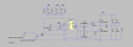
Please find attached the simulation schematic. The model for IR2110 used here was directly downloaded from the Infineon Website.
Please guide me as to what the issues might be here.
Thanks and regards
While running the simulation with the given schematics, I get an error on the HO side. The HO waveforms a square wave varying between 40 - 0V, even when the VCC is set at 15V.
When I remove the connection of the HO to the gate of the high side mosfet, the waveform varies between 15v-0v - as it should.
I have also checked the voltage between Vb-Vs and it is almost at a constant 15V.
I have varied the values of the Bootstrap capacitances, the gate resistance and the resistances between gate and source but the issue continues,
At this stage, when I check the value across Vs, I get the expected waveform with values fluctuating between 24V - 0V.
However when I introduce an ideal NMOS with the LT spice components, the HO works as expected with a voltage change between 15V-0V, however there is no switching on the Vs in this case and I see a 0V at the output.
Please find attached the simulation schematic. The model for IR2110 used here was directly downloaded from the Infineon Website.
Please guide me as to what the issues might be here.
Thanks and regards
Attachments
-
 92.6 KB Views: 8


