Facebook
 Google
 GitHub
 Linkedin
I really appreciate if someone can help me a bit with this project.
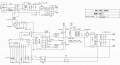
Its a half bridge topology DC-DC converter that takes 12V on the Input and transphorms it into a simmetrical 80V output (Maximum). The output voltage will be adjustable from ±18V to ±80V.
I am using the SG3525 IC for this design. The switching converter frequency is 100Khz. I wound the transformer myself and it works fine but there is one problem:
To drive a half bridge, a high + low side gate driver is needed. I tried to use IR2104 but there might be a problem with this SG3525 & IR2104 combination.
SG3525 gives out two square waves to drive two MOSFETs, and the duty cycle of both of those square waves will vary according to the feedback. But both outputs are designed only for LOW SIDE switching, so its impossible to connect them directly to the half bridge. So i decided to use IR2104 but the problem is that this gate driver has only one Input. Basically, a single square wave (That can change its duty cycle) can be feeded into the Input of IR2104, and that IC will be able to drive BOTH mosfet of the half bridge.
It seems like the IC is 'duplicating' the input square wave signal to switch both output MOSFETs alternately. So you can basically control a half bridge with just a single square wave, which is simpler. But here is the catch: SG3525 has TWO outputs. So i tried to connect only one output of SG3525 to the IR2104, thinking that nothing will change because the IR2104 will 'duplicate' the square wave again resulting in the same outcome. But this is probably where i'm screwing up. Something in my brain tells me that this setup is wrong. I tested the system (with the feedback set to 40V) and it works but the output voltage does not increase to more than 22V at 12V supply Input. If i increase the supply input, the output voltage rises as well, which is of corse wrong. I tried the same transformer in a different System and it works, increasing the voltage all the way to 80V or even more.
So the reason this System isn't working is because of the 'incompatibility' between the IR2104 and SG3525??
It seems like the duty cycle remains limited and wont rise up from a certain threshold.
Now i know there is a better IC which is IR2110. It has two independent inputs and outputs, which is probably what i need. It is still a half bridge driver, but it has independent channels.
So will the system work correctly after using IR2110? Can you help me figuring out if what i explained here is the actual problem? Because i already designed the PCB layout for the whole system, but in my test system i've got into this problem that i cant fully understand, it just confuses me.
This system is actually two equal circuits with their outputs connected in series. Thats why i am making them isolated. A single circuit takes 12V from the input and converts it into 18 - 80V. The feedback is designed around a comparator with its own isolated supply (B1212S - 1W) and an optocoupler.
Also, the MOSFETS heat up a bit too much.
They are 3.3 milliohms when fully turned on, and the gate driver drives their gates with a current of 2.5A (source and sink are both 2.5A). The gate capacitance of those MOSFETs is 9400pF.
So the fact that the MOSFETs do heat up a lot is probably related to the main problem i tried to explain here, i hope.
So i really appreciate if someone can help me understanding if THIS is the actual problem and if i can solve it by using the IR2110.
Because if there is another problem i will waste both components and PCBs that i am about to order for this project.
If my test circuit fully works then i am going with the final project.
Last edited: