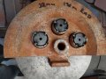
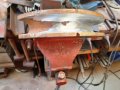
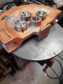
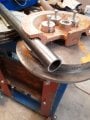
I already have a big bullseye painted on the roof of my house so when North Korea or others start firing missiles I can be included in their first strike and be done with it once and for all...
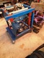
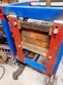
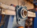
With the frame on wheels like that and the way the welds look on the worm gear box brackets, please, please make a video of your first test bend. It will be a Youtube viral.
Wish you lived close to me. I'd give you 3 flathead V8s. Got them years ago when doing engine swaps for different guys to use in some builds of my own. Getting too old now and will never get around to using them. No one wants flatties around here. Hate to scrap them though.
Thanks for your thoughts Shortbus.
Yes, always wanted to build a Ford flathead.
Started with the Cadillac, just because it was unusual around our parts.
Not so easy to source parts and custom items, so I made most of them or made them fit...
Those Caddies are really heavy engines which was what prompted me to build my gantry crane since I had nothing in my shop strong enough to lift the engine plus tranny (approx. 725kgs) in to the chassis.
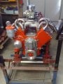
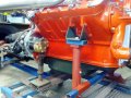
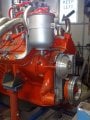
Many modifications made to this unit including twin carb manifold, late model mini starter, custom made timing chain cover late model SBC aluminium pulleys. custom made finned valley plates and custom stainless steel twin exhaust system. Oh and Chevy T700R4 auto tranny with over drive.
I like you have a bias toward the engines no one else use. I like 6 cylinder engines be they V, straight or boxer style.
I built from the ground up a rail dune buggy using a Chevy Corvair engine. Then there was a Jeep with the 292 Chevy 6 with home made 4barrel sheet metal intake and headers. And home built Chevy 4 speed to Jeep transfer case adapter, even built the main shaft for the adapter. If I live long enough to finish it I have a 1937 Ford pickup that will have a V6 and 5 speed transmission in it. The frame has been modified to use a Mustang front suspension and a 1989 Thunder bird independent rear end. Getting too old and bad health.
But will pretty soon have a bucket list thing accomplished, one from my teenage years. There are pictures of the progress in another thread in the forum, about Covid projects. I'm building a crawler out of a lawn tractor. Just getting to the end of the project.
Well, I now have a complete chain and sprocket drive to power my output shaft.
A test run showed that it was running at 2.75 RPM.
I was shooting for 2 RPM, so I guess that ain't bad and under load it may come down a touch...
No pictures to show yet, but I have settled on a slight design change.
As the current unit stands, it has a limitation on being able to perform a secondary bend where the tube needs to point downwards as the bench/table is in the way.
On many other units I've seen this is corrected by having the final drive arms kind of cantilevered over the edge of the table providing some space around the unit to handle about a 40 inch length of tube that could be directed towards toward the floor if a 2nd bend is required (depending on bend combination and configuration), so taking this possibility into account, I decided to bite the bullet now and build into my machine that additional feature.
Easier to do it now than to have 2nd thoughts later and try modifying it then...
So now, I am looking for some more RHS, flange bearings, more chain and another sprocket.
Slow progress as usual, but still heading in the right direction.
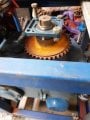
As part of my redesign. I discovered that I would need to lower the height of my large reduction gearbox in the frame.
Fortunately, something told me when I started this project that I should include multiple holes in the support plates holding this large gearbox.
I have dropped it one set of holes and have been waiting to get hold of the extra bearings I seek.
I now have the 2" flange and bearing which will give me a 3rd bearing on the main output shaft, which I have decided on just to take some of the load off the old original bearings in the gearbox.
Now I have the 2" bearing here at home and needed to run the shaft and hold a file on it to clean the shaft and get the bearing to fit, I find that I will need to drop my gearbox down an additional hole if I want the bearing to sit below the table top height of the frame.
I guess it beats having to cut a hole in the top for the bearing to stick thru.
I was not able to source flange bearings easily locally (imperial stuff in some sizes is hard to come by) for the addition shaft and sprocket that I will be adding into the cantilever final drive, so I have ordered them on Ebay and now just need to wait for the mail man.
As always, one adjustment has an affect on other things, so now I find my chain is too long as the gearbox has been moved closer to the motor. Rather than shortening the chain, I have an idler sprocket and hope to use that to adjust the tension on the chain and keep my options open.
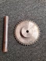
The other task I managed to complete was to install the 2nd hand sprocket I had given to me onto the 2" output shaft and make a odd kind of key to work with both the shaft and the sprocket.
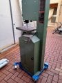
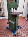
Still waiting for the mailman, so I decided make a trolley for my recently purchased metal cutting bandsaw.
It is just too heavy and bulky and probably wont be used regularly, so I figured that it would be nice to store it away.
Nothing fancy but it works a treat.
My bandsaw trolley has worked out really well and so my next side project will be to add wheels to my recently acquired sheet metal guillotine.
Not that I will use it daily, so it is best made mobile to maximise shop space and it is a heavy sucker, so wheels seem to be the way to go.
In the meantime the mail man has shown up and and I am in the throws of making some progress on my bender, so I can post some more pic's very soon, so stay tuned...
Thanks, it is a 346 Cadillac flathead engine.
I have rebuilt it from scratch and along the way, I have had cast my own modified timing cover and valley plates to help with the modifications and give it that hot rod look.
They are a big heavy engine and like all old engines when rebuilding them, you end up spending twice the money compared to building a modern engine with the result of getting only half the horse power...
It is a passion otherwise you would never do it.
I did some reading around the internet before starting the rebuild years ago and found an article which was written reporting that the Italian Mafia preferred a the LaSalle car with a 322 engine over the Cadillac 346 engine of the same era.
They seemed to think it made for a better get away car.
I have no idea except to figure that just maybe the 322 bore and stroke was a better combination than the 346 and that the 322 may rev better, so on the strength of nothing more than that article when rebuilding I decided to sleeve all my 346 cylinder back to 322 in the hope that maybe I would be better off.
To this day the engine is in a project car but has not been finished to drive as yet, although it has been started and will run. It has some carby teething issues that I need to get around to addressing...
The best way i found to set up a carb is using the Propane Enrichment method. You need propane with a regulator and on/off valve and a port on the engine. You adjust the regulator for max rpm and turn off the propane. The RPM change needs to be small, like 25 RPM. This method assures the throttle plates are in the idle system.
Finally, I have a bit to show now.
This build is a pretty adhoc process as I have no plans or drawings and I am just kind of drifting along with it.
I have acquired the last of my sprocket needs, but as usual it comes with a need for a keyway and also a larger hole to be bored in it.
As my small lathe does not have enough swing and the sprocket teeth will hit the bed, I needed to phone a friend with a larger lathe so today we machined out the larger hole to fit my idler shaft and and now have a pair of flanged bearing blocks to support it once setup.
I also have another flanged bearing block that I am using on my large reduction gearbox out put shaft which i think I mentioned was my intention previously.
The hole in my lathe chuck was not large enough to accomodate my idle shaft material (being 1 7/16" diameter), so again I had to rely on the generousity of my friend to put it in his lathe and machine centres at both ends for me and then bore out an 11/16" hole about 2" deep as I need to cut a 20mm course thread (as I have some M20 threeaded rod I will use to make a hold down bolt) in it as a means to hold down my forms when in use.
Sorry about jumping from inches to millimeters but it seems to be the way of the world these days for me when making something out of nothing and using what is available to me...
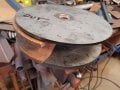
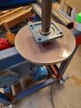
I have been waiting for 2 hole saws to arrive in the mail which have now turned up, one of which will be used to cut a 37mm large hole in some circular plate off cut discs that I got from my local scrap yard as I intend to use them for my rotating table as well as spacers and adapters to accommodate the various forms I intend to use.
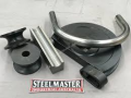
I was lucky enough to find a cast aluminum half circle form for a cheap price which will save me many hours of machining and it nearly matches the diameter tube which I anticipate I will use often.
Being aluminum, I am concerned it may split under load (with the heavier wall tube I anticpate bending) so I have decided to use a couple of those circular discs to sandwich it top and bottom as a means to support it.
As I mentioned the form radius was about 1.5mm too small for the tube I had in mind for it, so I have used my grinder with a flapper disc to take a little meat off it all round and then hand polished it with sand paper.
My selected tube now fits and I hope will work out nicely.
The other hole saw will be used to make some larger holes in my support arm that will carry my pair of flange bearings and the idle shaft.
It will be much clearer to all concerned once I make a little more progress and have pictures to show.
That last picture with the tube in the die, has me puzzled. Thought you were making a wiper die type bender? What you were wrongly calling a mandrel bender. With a wiper type bender the wiper block has to be able to support the outer side of the tube, as the picture, 20210717_130749-jpg, shows it this won't be possible.
When I bought my JD2 bender the dies weren't all that expensive, considering how hard they would be to make/DIY. Especially if you only bend 1 or 2 sizes of tube. Here's a link to JD2 and all of their dies, didn't look at prices though because don't know which ones would be the closest fit for your project. There are or were some other companies out there making similar inter changeable dies for those machine too. https://www.jd2.com/tube-and-pipe-dies
You could be right regarding your observation of my project, however it is by no means finished just yet.
I am not sure what defines a mandrel bender other than it being a machine that employs that bullet shaped slug that runs inside the tube at approx the tangent point of the bend while being bent to ensure the wall integrity during the drawing/bending cycle.
Since the form I have mentioned is a half circle only, in one position it can be installed as you suggest, where the form rolls the tube around itself, however setup in the oppoiste senario and then the form will require the wiper stroke as you mention.
To be totally honest with you, I have been so enthausiastic to try this unit out to see how close I have come to getting the function of it right/workable, that yes, I was not intending to use the wiper stroke initially due to my eagerness to test it.
That is not to say that I am not going to try setting this machine up with the a wiper mechanism, especially when it comes to dealing with larger than 1 1/4" outside diameter tube.
My aim is to be able to bend 1 1/4" & 2" thick wall tube at approx 1/8" wall and then once I have this unit operational to my satisfation, I will aim to bend 2 1/4" & 2 1/2" thin wall stainless steel exhaust pipe.
When it comes to access to forms and the like, sadly I do not live in the USA and hence the availability of inexpensive good quality equipment and accessories is almost unaffordable and hence me building this whole project from scratch.
I was lucky enough to have scored a bunch of old forms, most of which I will not use from an estate sale. These forms were some of the accessories used by an old factory here in my city which made metal tube furniture in the 1970's. I will need to adapt any that I like to fit my turn/wipe mechanism which I feel is achievable.
Right now I am in the hands of the Gods and counting on luck being on my side...
I have a little more progress heading in the right direction.
Definitely not earth shattering but it is stuff that needs to be done.
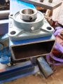
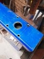
I found a large piece of scrap RHS material that I intend to use as a cantilever member off the side of my main chassis as a means of providing clear movement of tube when doing a 2nd bend as some situations while require clearance for the bending material.
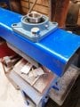
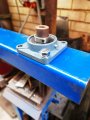
I needed to set up a pair of flange bearings with one on top and the other underneath and create a hole for my idle shaft to pass thru.
Not rocket science, however it gets a little tricky trying to get holes etc from each side to match up exactly with one another.
I got within 0.5mm from what I can tell so I am happy with that.
I am using M14 bolts to match the flange bearing holes and have tapped threads into the RHS as space is limited and nuts would not fit.
I am not sure what defines a mandrel bender other than it being a machine that employs that bullet shaped slug that runs inside the tube at approx the tangent point of the bend while being bent to ensure the wall integrity during the drawing/bending cycle.
Since the form I have mentioned is a half circle only, in one position it can be installed as you suggest, where the form rolls the tube around itself, however setup in the oppoiste senario and then the form will require the wiper stroke as you mention.
Your correct when you say a mandrel bender has the internal "bullet" that's what makes them a mandrel bender. But even a mandrel bender uses a wiper block on the out side. all of the original links you gave showed a wiper bender, so called because they have a flat, straight block that has 1/2 of the tube outside diameter in on face. It's the wiper that is actually making the bend, not the mandrel. A manual copper tube/ brake line bender is a good example of how the wiper does the bend and keeps the tube from flattening too much on the outside of the radius of the bend.
The other type of tube bender is the type most muffler shops use that kind of crushes the inside of the bend to make the radius.
I am definitely missing your point here.
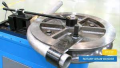
My take is that I am building a rotary draw pipe/tube bender that may or may not employ a mandrel.
There are certain tube and form combinations that will definitely require the use of the mandrel to help ensure a quality bend, yet it would appear that depending on expectations and wall thickness a mandrel may not be required on others.
If my machine is not finished yet I am wondering how you are so certain that my machine will or will not be classified as a mandrel bender???
Some rotary draw benders have an obvious wiper arm visible, yet it is possible to draw the tube using other hold methods.
I just can not see how they are any less a mandrel bender if employing a mandrel device inside the tube...

 Facebook
 Google
 GitHub
 Linkedin