Help with reversing a dc motor with limit switches

Thread Starter

Pants01

Joined Dec 21, 2024
7
Hello good people. At the risk of everyone roll their eye and groaning, I have a question on a simple circuit I'm trying to build, but as you may have guessed, I know very little about electronics, my background being more mechanical. I hope I've posted this in the right place. I've done quite a bit of research and this where I'm up to now.

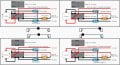
Right, here we go - I'm hoping to build a circuit that controls a DC motor (or stepper motor) with:

* 2 limiting switches
* 1 simple (2 contact) on/off switch for direction control (SPST switch?)
* 1 DSDT relay.

Simply put, I need the on/off switch to command the motor to drive a worm gear fully to one direction where it will be stopped by the limiting switch. Then when the on/off switch is flipped the motor reverse direction and drive the worm gear to the other end where it will be stopped with the other limiting switch.

I have found a simple circuit plan (clearly not my work) that would appear to perfectly suit my needs. I’ve attached the (corrected) wiring diagram here (if anyone is interested link to video here is:
).

While in my simple little brain I think (think being the key word) I understand the basic schematics and principle of the circuit, I'm having trouble with the practical side of the wiring. Firstly, based on my description of what I need described above, do you clever people think that the attached schematic/diagram is correct for what I need? Secondly, if it is, the wiring diagram attached shows both limit switches with only 2 contacts, but I can only find 3 contact ones. If this is the case, how do I wire these and especially the DSDT? I don’t know how time consuming it is but would it be possible for someone to scribble how to wire the 4 components correctly?

Many thanks in advance if someone is able to help.
 

Attachments

Tonyr1084

Joined Sep 24, 2015
9,744
Welcome to AAC
What voltage are you planning on using?
I don't think you need a relay at all. A simple DPDT switch can be wired easily to reverse the direction of the motor. Limit switches can disrupt power when a limit is reached.
[edit] that video is too long and the presenter is not very knowledgeable on the subject. They DO understand what they're doing but they are not well versed in verbiage to explain it. So give me some time and I'll bang out a drawing showing how to set up a reversible motor with limit switches using one switch, two limit switches and two diodes along with the motor and power supply. [end edit]
 

Thread Starter

Pants01

Joined Dec 21, 2024
7
Hello Tony, thanks for the reply. The whole thing would be powered off a 3S Lipo so around 12V.
As for the relay (from my little understanding) I thought this was necessary for 1) reversing current direction and 2) commanding when it should be done (i.e. by the simple on/off switch). You have thrown a cat amongst the pigeons now with the "simple DPDT" and I'll have to go and do some research on what it is and how it works. Thanks.
 

Thread Starter

Pants01

Joined Dec 21, 2024
7
Oh Tony, thank you very much, this is exactly what I need. I've just been reading up on DPDT switches and it's all rather complicated. Many thanks again.
 

Tonyr1084

Joined Sep 24, 2015
9,744
Below are a few diagrams. The upper left is a simple DC Motor reversing circuit showing a Clock Wise rotation. The upper right drawing is the same circuit with the same CW rotation and shows a direction of travel. When LS2 (Limit Switch 2) is touched, it opens, thus interrupting the flow of current and shuts the motor off. The lower two diagrams show the motor and direction of travel in the opposite direction. When LS1 opens the motor stops. The diodes only provide directional current of an open switch. Once the switch closes the diode is bypassed.
Screenshot 2024-12-22 at 10.51.02 AM.png
No need for a relay and a switch to run the motor in one direction or the other. The diagram the YouTube Boob shows has current flowing at all times when the motor is set to run in one direction. True enough, when the switch is turned off the relay drops out and the motor runs in the opposite direction. That's a poor design because in one configuration current is always being drawn. If you're running from a battery this means the battery will be drained.

The above circuit shows that the motor will run in one direction when switched to that direction. When the movement reaches the limit the motor stops and no more current is being drawn. The ONLY drawback of this circuit is that the motor must move to one end or the other. You can't stop it in any one position. If you wish to stop it mid-way a simple push button Momentary Closed button will only move the movement in either direction, depending on the position of S1 (shown only in the upper right diagram). Guess I missed including S1 in all the diagrams. Oops. Nobody's perfect. So S1 sets the direction. The momentary PB runs the motor until a limit has been reached. If you are not pushing the momentary PB then no current flows and if battery powered, no power is wasted.
 

Tonyr1084

Joined Sep 24, 2015
9,744
NOTICE: I think I might have the diodes backwards. Let me investigate further.
[edit]
Nope. I think it's right. If I'm wrong other members here will correct me.
[end edit]
 

LesJones

Joined Jan 8, 2017
4,511
The wiring diagram you show should work. Make sure that the relay that you use has the same connection layout as shown at the top of your diagram. The diagram only shows the contacts that are used on the limit switches. If the mechanical layout is such that the lever on the limit switch is pressed when the limit is reached then use the C (Common) and the NC (Normaly closed.) connections on the limit switches. With the diagram that you have posted you do not need the two diodes. The alternative way the tony is suggesting reduces the number of wires between the DPDT (Relay or switch.) This is usefull if the switch is a long way from the motor and limit swtches.
Les.
 

Tonyr1084

Joined Sep 24, 2015
9,744
The alternative way the tony is suggesting reduces the number of wires between the DPDT (Relay or switch.) This is usefull if the switch is a long way from the motor and limit swtches.
The reason why I opt for no relay is that for the motor to travel fully one way the relay must be ON and for the motor to travel fully the other way the relay must be OFF. So that in one instance the relay is going to always be on. In the other instance the relay is off and no current is wasted. The TS did state
The whole thing would be powered off a 3S Lipo so around 12V.
So it's my opinion using a relay in this case would prove wasteful half of the time. Also, the motor movement will be fully one way or fully the other way.

I'm fussy about my drawings. I've redone it to include a momentary push button, normally open, so that a user can slew the movement to any point along the way and stop at the desired point. The limit switches simply "Limit" the amount of possible travel.

So here's the revised drawing with MPB1-NO (Momentary Push Button-Normal Open):
Screenshot 2024-12-22 at 11.28.26 AM.png
 

Tonyr1084

Joined Sep 24, 2015
9,744
My bed inclines and reclines. I can fully incline it or fully recline it. I can stop at any point in the midway. It moves only when I say it should and it stops moving when it reaches a limit or I let go of the button.
 

Tonyr1084

Joined Sep 24, 2015
9,744
https://www.amazon.com/gp/aw/d/B07NVD4YZZ/
This is a microswitch. It can be used in many applications. The drawing shows a lever on the switch which makes the switch more sensitive to positioning. As Les said, make sure your limit switches use the C and NC posts. That way the switch is working until the limit is reached, then it opens.
If the lever on the limit switch is pressed when the limit is reached then use the C (Common) and the NC (Normaly closed.) connections on the limit switches.
If on the other hand the limit switch is held closed until the limit is reached, the opposite would be the case, the C and NO. If this confuses you I can draw out another picture.
Here's what a microswitch with a lever looks like:
Screenshot 2024-12-22 at 11.45.55 AM.png
 

Thread Starter

Pants01

Joined Dec 21, 2024
7
Even though this is a lot to digest for me, I'm sort of getting the gist of it. Thank you (both) very much for taking the time to explain and draw out the circuit, it's very helpful. I'm going to start to have a hunt around for components and have a play around.

Just to explain what I'm doing (which might shed light on how this is supposed to work), I'm planning on using this circuit for retractable undercarriage for an rc aircraft. I won't need any mid point stopping, not only is it not required but the circuit/system will be deployed remotely (obviously). The idea would be for the DPDT switch to move the motor to extend the undercarriage fully down until it is in position as dictated by the limit switch. The fact that power will not be used when the system is not being used is very important (thank you once again). Once the gear needs to be raised the DPDT switch will be selected and drive the motor the other direction raising the undercarriage until is fully seated in the closed position (as dictated by the other limit switch).

For the diodes I take it as long as they are rated for the correct voltage, diodes are diodes or is there other magic at work here that I would be aware of?

Thank you once again.
 

Tonyr1084

Joined Sep 24, 2015
9,744
I'm planning on using this circuit for retractable undercarriage for an rc aircraft.
This changes a lot. Will have to reconsider things.
For the diodes I take it as long as they are rated for the correct voltage, diodes are diodes or is there other magic at work here that I would be aware of?
Diodes are rated in max voltage they can handle forward and reverse. Exceed those and you blow them out. The main concern for a diode is how much current it can tolerate - again, both in forward and reverse bias (voltage).

I would assume RC aircraft controllers have multiple levers and switches for such operations. The gear retraction should be done by servo. All this time I had in mind a regular DC motor, something on the order of a small CD Player motor up to a much bigger DC motor. You want to avoid weight. So getting the correct controller would be the ideal approach. One with a landing gear function on it. If you're looking to make your own - I'll have to bow out of this conversation. I haven't the knowledge or experience on such matters.
 

Thread Starter

Pants01

Joined Dec 21, 2024
7
Right, a quick search on eBay for components and I've come up with this for a quick trial and error play about on my bench (pic attached). Do you think that this would be suitable? Also, last question (for now), am i correct in assuming a stepper motor would be more advantageous? I get the impression they are able to handle bigger loads but their connectors are more complicated than a simple +ve and -ve. Can they be used as simple DC motors or is that not possible? Thanks.
 

Attachments

Thread Starter

Pants01

Joined Dec 21, 2024
7
This changes a lot. Will have to reconsider things.

Diodes are rated in max voltage they can handle forward and reverse. Exceed those and you blow them out. The main concern for a diode is how much current it can tolerate - again, both in forward and reverse bias (voltage).

I would assume RC aircraft controllers have multiple levers and switches for such operations. The gear retraction should be done by servo. All this time I had in mind a regular DC motor, something on the order of a small CD Player motor up to a much bigger DC motor. You want to avoid weight. So getting the correct controller would be the ideal approach. One with a landing gear function on it. If you're looking to make your own - I'll have to bow out of this conversation. I haven't the knowledge or experience on such matters.
Opps, just saw your reply as I hit send on mine. The short answer is yes, I have to design and build my own as servos cannot be used other than for moving the DPDT up or down. The potential large loads will be reduced through mechanical gearing of the worm gear so I don't think there will be any larger (than usual) loads typical of servos. I'd be very surprised if it drew more than 1 amp, 1.5 if it goes wrong.
 

MisterBill2

Joined Jan 23, 2018
27,271
Another way that might be possible is a gear motor and a crank. Half a turn to lower and half a turn to raise. No limit switches and no chance of moving to far. But it would take a lot of gear reduction and a fair amount of torque.
 

Thread Starter

Pants01

Joined Dec 21, 2024
7
Below are a few diagrams. The upper left is a simple DC Motor reversing circuit showing a Clock Wise rotation. The upper right drawing is the same circuit with the same CW rotation and shows a direction of travel. When LS2 (Limit Switch 2) is touched, it opens, thus interrupting the flow of current and shuts the motor off. The lower two diagrams show the motor and direction of travel in the opposite direction. When LS1 opens the motor stops. The diodes only provide directional current of an open switch. Once the switch closes the diode is bypassed.
View attachment 338657
No need for a relay and a switch to run the motor in one direction or the other. The diagram the YouTube Boob shows has current flowing at all times when the motor is set to run in one direction. True enough, when the switch is turned off the relay drops out and the motor runs in the opposite direction. That's a poor design because in one configuration current is always being drawn. If you're running from a battery this means the battery will be drained.

The above circuit shows that the motor will run in one direction when switched to that direction. When the movement reaches the limit the motor stops and no more current is being drawn. The ONLY drawback of this circuit is that the motor must move to one end or the other. You can't stop it in any one position. If you wish to stop it mid-way a simple push button Momentary Closed button will only move the movement in either direction, depending on the position of S1 (shown only in the upper right diagram). Guess I missed including S1 in all the diagrams. Oops. Nobody's perfect. So S1 sets the direction. The momentary PB runs the motor until a limit has been reached. If you are not pushing the momentary PB then no current flows and if battery powered, no power is wasted.
Hello Tony. Just a quick note to let you know I followed and built your circuit in response for my call for help and it has worked absolutely perfectly, exactly what i needed/wanted. Thank you once again for taking the time to read and answer and put together the wiring diagram. I will post a pic or two when I can later to show you your masterpiece.

Thanks also to LesJones and MisterBill.
 

bz400s

Joined Apr 19, 2025
2
good afternoon, i like pants01 am much more mechanical than electrically minded so please bear with me. i have a homebuilt sawmill which i am adding powerfeed to the carriage using a mobility chair brushed dc gear motor. the circuit u designed for pants 01 is basically what i need, but with a few differences. this one is 24v via a step up converter, which then powers a variable speed controller. my question is the diodes used around the limit switches. im not sure what amount of current this motor will draw, as i can't find any specs. I've spent several hours looking. the donor motor(s) came from a jazzy select elite & rated at 24v. would anyone have any ideas? i appreciate your time in advance.
 
Top