 Facebook
 Google
 GitHub
 Linkedin
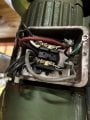
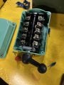
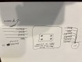
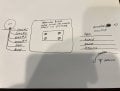
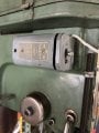
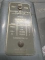
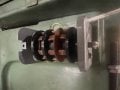
Hello, I am working on a mill/drill and switching the wiring from 115v to 220v. The motor has four numbered black wires #1-4 plus a red and a gray Comming from inside the motor. Total of six wires. Picture #1. The motor needs to be hooked up in such a way it has forward/stop/reverse. The switch is a rotary switch that is new because the original switch was broken Picture #2.
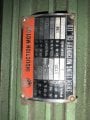
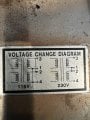
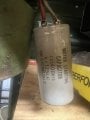
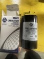
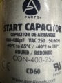
I have a new 220V capacitor as well to replace the original 115v. The wire plate in the motor shows 115v and 220v installation. The new switch has numbers but no wiring diagram.
I have a new 220V capacitor as well to replace the original 115v. The wire plate in the motor shows 115v and 220v installation. The new switch has numbers but no wiring diagram.
Attachments
-
 560.2 KB Views: 11

")


