How to use limit switches in a project circuit?

shortbus

Joined Sep 30, 2009
10,049
Simarly, parting off, now that can be a real art.
I had all but given up trying to be any good at that, but now after much persistence I finally enjoy success when parting off.
Like many things on lathe work it's all about the tool its self. On a standard parting tool as it comes from the factory most people grind a small "hook" or chip breaker on them, and then to sharpen it the grind the hook deeper, that's how I was taught in high school. But that is the wrong way.

Where I served my apprenticeship they had a retired guy that came in when needed to help out with the work load. He ran a lathe his whole time working, knew very little about a mill. He taught me so much changed how I did lathe work. A parting tool one held in a parting tool holder has a grind on both sides, to make clearance as it goes deeper. then there is two angles on the top for the clamp/eccentric bolt. To sharpen you just want to flatten the top of the tool, to just remove those angles at the tool point. The when the tool bit gets dull you just grind the face of the tool. Old Dewey taught me a lot of other tricks too.
 

Thread Starter

fiftyv8

Joined Jan 29, 2018
223
I wish I had a mentor when I first took on the lathe.
Sure would have saved going the long way around and probably saved a big pile of swarf on the way...
More project progress coming up soon.
I've had a couple of slow weeks .
 

Thread Starter

fiftyv8

Joined Jan 29, 2018
223
Well it is time once more to post my progress picture and try to stay on subject.
Althoufgh straying off topic can be educational when information and ideas are offered.

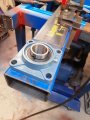
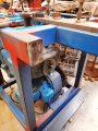
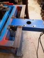
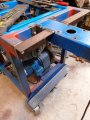
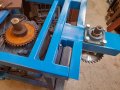
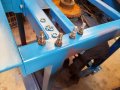
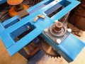
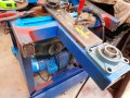
So, I have worked out a way of mounting my idle shaft support bracket and have proceeded to fabricate it and get it test mounted onto the main body of the bender.
I was at a loss as to what direction to go in and honestly had a couple of better ideas including a fold away arm setup, but since I am still not 100% convinced I am on a winner yet I went with a simple design.

It looks to me like it will hold together for a test run soon.
 

Attachments

Thread Starter

fiftyv8

Joined Jan 29, 2018
223
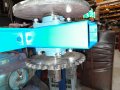
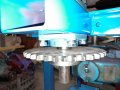
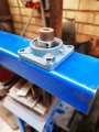
The idle shaft is set up remotely from the frame body, so it is capable of providing a rotating table if you like, that has a clear area around it to cover the senario that a piece of tube already has 1 bend in it and the bend is turned toward the floor and is able to still make a 2nd bend without anything getting in the way of the tube when rotated.

The bender will still be capable being loaded to make a 2nd bend.
A lot of these machines have this capability and I just figured that since I had already started I should attempt to provide it too.

It is probably not possible to be able to accommodate every bending situation, but since I have a long term dream of being able to bend exhaust pipe, then I figured that my machine should be at least able to do this in 2 dimensions.

There are other machines that dont appear to have that ability, yet some have such a small footprint that they still can achieve a degree of clear rotation.
Sadly, my unit is a bit big and cumbersome so I need to do it a bit differently, otherwise I could be turning bends from that hole you would see previously in my piece of table plate.
The way I designed my table it is still a possibility if required.
 

Attachments

Thread Starter

fiftyv8

Joined Jan 29, 2018
223
It is amazing what a coat of paint does to make my work look better.

I am at the stage now where I need to decide on a method of attaching the lower sprocket and the upper turntable plate to the idler shaft.

If there is anybody out there with an informed opinion, I be happy to hear from you.

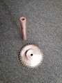
With the lower sprocket, I was planning to just use a 8mm keyway since the boss body of the sprocket has quite a bit of thickness/depth to it for what should be enough purchase, however it has crossed my mind to use two keyways on the opposite sides of the shaft, but not sure if that would be over kill???

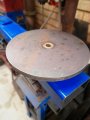
The upper turntable plate is where my concerns are raised, since my idler shaft is 36mm diameter (1 7/16") and the plate is 16mm thick (5/8").
I pretty much need a flat finished surface top and bottom as each surface will meet other flat surfaces.

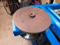
Right now, I have a shaft that is protruding thru a neat hole in the turntable plate.

Options that I see are as folows;
1. Vee out both sides of the turntable plate and weld it, then machine the surfaces flat?
2. Install one or two keyways and hope for the best?
3. Square out the hole and add weld metal to the shaft to make a square head on it?
4. A suggestion from the audience...

My buddy seems to think decent welds in option 1 would be good enough, but I just am not convinced right now...
 

Attachments

shortbus

Joined Sep 30, 2009
10,049
Options that I see are as folows;
1. Vee out both sides of the turntable plate and weld it, then machine the surfaces flat?
2. Install one or two keyways and hope for the best?
3. Square out the hole and add weld metal to the shaft to make a square head on it?
4. A suggestion from the audience...

So far you haven't seem to like my suggestions but I'm giving them from years of making industrial special machinery and my own stuff. so here goes

1. Unless your using TIG welding you will probably end up with a warped plate.

2. How will you make sure both the shaft and hub keys are directly opposite each other or otherwise a good fitting key? If one is off it will need to be fit to the other or if made sloppy enough to fit one will shear to make both hold the load. And removing extra metal from the shaft for a second key makes a weak point.

3. Can you accurately make a square hole to fit your now square shaft?

4. If doing this for myself with limited machining capability, I'd probably buy as large a sprocket as I could afford with a QD hub and bushing to fit the shaft. And bolt the plate to the sprocket. They are a proven way to transmit power, using both a key and the taper to grip the shaft securely. https://www.regalbeloit.com/brands/Browning/products/Q-D-Bushings
 

Thread Starter

fiftyv8

Joined Jan 29, 2018
223
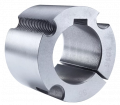
When sprocket shopping earlier in my project, I was offered a similar item (pictured below), but was then told it was not available in the imperial size that I required and then told the the closest size was not in stock.
Living in the USA is a garden of Eden for just about anything that you could dream of, I should know as I have visited your great country 14 times.
Not to mention how cheap everything appears when compared to stuff in my neck of the woods.

Taper Lock Bushes
Chain & Drives have Steel Taper Lock Bushes for heavy duty applications.

1629736344672.png1629736344672.png

There is no doubt that you are right in offering such a solution, however with the limitations I am encountering here, I will need to seek an alternative solution.
I am leaning toward trying the square drive insert idea.
By making a square plate of the same thickness as my turntable approx 2" x 2", I can hold this in my lathe and machine in bevels for welding and machine off weld excess to obtain flat mating surfaces.

I can pretty much make this small plate a perfect square shape without too much trouble.
It will require much more effort creating a square hole in my turntable, but I guess I am up for it as long as I can be convinced it is an OK idea as a 2nd choice lets say.

I agree that two keyways kinder made me nervous about how they might workout.
I enjoy watching YouTube videos posted by guys in 3rd world countries doing stuff with very little and I remain amazed with some of the ideas and how they improvise with limited resources.

So, I will seek out a scrap piece of 16mm (5/8") plate and get started in the next couple of days.
Tomorrow I get my 2nd Covid jab and going by my 1st jab, it will knock me for a couple of days.
Nothing serious with my last jab, but I was right off my game for about 4 days, but not immediately after the event.
Who knows with this stuff.

Anyway, fingers crossed both for the jab and also for this being my possible solution.
Make no mistake Shortbus, I am not trying to frustrate you and appreciate you interest and concern and more importantly your informed comments and the fact that going forward I feel your hand of experience on my shoulder whether you realise that or not.
So thankyou for that, Russ.
 

shortbus

Joined Sep 30, 2009
10,049
By making a square plate of the same thickness as my turntable approx 2" x 2", I can hold this in my lathe and machine in bevels for welding and machine off weld excess to obtain flat mating surfaces.
If I understand you correctly, your going to make a square plate and then weld that to the end of your shaft, and then bolt the square plate to the "turntable", correct? So if that is the idea let me give another that doesn't require welding. I'd go to the car/truck wrecking yard and find an old rear drive axle and cut it down to the length needed. Then you could bolt the turntable to the flange that the wheel and brake drum bolted too.

Your more correct than you even know about the USA being a tinkerers dream place. Withing a little over a 100 mile radius there are places selling brand new or lightly used things at pennies on the dollar. And scrap yards every where. All from the closing of our industrial plants.

But this is not meant as a put down, just a comment. If things are so hard to come by there, why do you keep inventing new ways of doing things? Ones that don't use what you all ready have spent money on? I have always found that I get an idea and work it out before buying stuff. Or if I get stuff that I can incorporate in an idea free or at too good a price to pass up, I then change the sizes of things to fit what fell in my lap. All of this before actually spending my money.

Most things I do in analog CAD, Cardboard Aided Design, to prove the fitment. Or smaller things I draw out at a larger scale on paper to prove out a design. But like I said not trying to put you down just explaining a different way of doing things.
 

shortbus

Joined Sep 30, 2009
10,049
Again just an idea. Instead of welding the shaft and then machining it square then cutting the hole in the turntable and welding yet again. Why not cut a ring of your 5/8 plate, one with a press fit hole in the center to press onto the shaft and weld it. The OD of this plate would be smaller than the turntable and have 4 or 5 tapped holes in it, like a car wheel pattern. This smaller diameter plate would be easier to face off in the lathe to true it up and then by putting the same hole pattern in the turntable using flat head cap screws it would then bolt to the shaft assembly. This would prevent any warpage in the turntable from welding on it.
 

Thread Starter

fiftyv8

Joined Jan 29, 2018
223
Hmmmmm, not a bad idea at all.
Not feeling so good after my jab as anticipated, so I may drop off the radar for a while lets see anyway.
I will use this time for contemplating my/our next move.
 

Thread Starter

fiftyv8

Joined Jan 29, 2018
223
Like always, I am a little late, but do have some progress to share.

I've progressed in the direction of my square drive option and have spent most of my time not feeling so good after my 2nd Covid shot, but needed a distraction to take my mind off my woes.

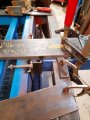
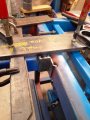
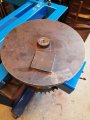
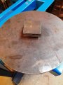
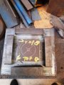
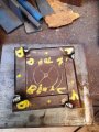
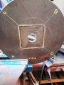
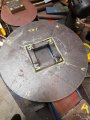
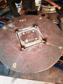
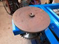
So, I have continued by preparing the center square hole in my turnatable plate.
I started by cutting a fairly large square chuck of metral out from the centre of the turntable plate.
The cut out size was determined by the fact that my dive was 55mm square and then I wanted to fabricate a fitted frame around it, made up of 16mm square pieces that I cut up out of some flat bar I had.

I felt this would be the easiest method to create an accurate square hole without the need for too much hand filing etc.
The result so far seems to speak for itself as it went togther quick and easy with not so much effort required apart from welding and some flapper disc grinder work.

The size of the cut out worked out well as it matched pretty well with the size of my 125mm cutting discs, so a cut from one side that made it part way thru, then a cut from the other side which took most of the metal out and then I used my jigsaw with a metal blade to clean out the corners and the large square piece was removed.

The accuracy of the disc cuts was not so critical as it gave me a little wiggle room to get my true centre and drop my frame in and tack weld it into position.

No special skills required, just proceeded with caution and remained patient.
 

Attachments

Thread Starter

fiftyv8

Joined Jan 29, 2018
223
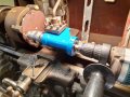
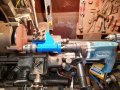
I finally got a chance to try out one of my recently fabricated gizmo's.
Both gizmo's have had a coat of paint since you last saw them...
I could have done this task another way, but I just took the opportunity to see how it would go.

It went well with no issues.

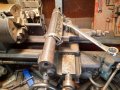
Just a bit of fun this time, but it will serve me well in the future as I have gotten up enough courage to make a new chuck face plate for another chuck I have acquired, but it does not have a face plate that will fit my lathe.
I will need to drill several hole in a flange arrangement so this will be perfect for the job.

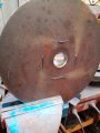
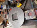
The plate setup and pictured in the lathe is for the bender project and will sit below the turntable plate and be attached to the underside of my small square drive to prevent the turntable plate from dropping past the square drive.
I have added some flange holes as a means of locking the turnatable plate to it as it will rarely be removed if ever.
 

Attachments

shortbus

Joined Sep 30, 2009
10,049
Again don't take my comments the wrong way, just trying to help or understand your thinking.

What does the big square part welded to your shaft and then the square gets welded into a hole cut in the turntable do?? Again from my experience and normal engineering practice it would be a less than ideal way of doing things.

When you first mentioned adding a square to the end of the shaft by welding, I thought you meant you were going to build up some weld then machine it into a square.

But what you did? Why? Even after you weld the big square into the turntable plate all of the force in use is still up to the weld on the shaft. The welding of that into the plate is just another place to get a distortion from, due to the heat of welding. Not an ideal situation from my point of view.

Another hint. When you have to weld something like your shaft to a plate, turn the end of the shaft down to a depth of the plates thickness, if the shaft diameter allows it. Doing this gives a better chance of the shaft being welded square to the plate.
 

Thread Starter

fiftyv8

Joined Jan 29, 2018
223
My lathe is not big enough (swing wise) to machine back the welds had I just welded the large disc turntable directly to the shaft. This way I have square drive welded to my shaft and I can fit that into my lathe to clean it up both sides.
I have no intentions to weld the square back to the disc, ithere just does not seem to be any need.I refer you back to my previous post, last paragraph relating to the pic's attached.

The plate setup and pictured in the lathe is for the bender project and will sit below the turntable plate and be attached to the underside of my small square drive to prevent the turntable plate from dropping past the square drive.
I have added some flange holes as a means of locking the turnatable plate to it as it will rarely be removed if ever.


Next, the turntable plate will have 4 studs or dowells installed in it which I have made from some tensile bolts by turning the threads off.
The dowells will form the basis for all interchange devices that may be used to bend whatever tube I choose with whatever form or device I make or acquire from whatever source.

I just need an attachement point that can be universal and allows an easy way to attach any devices I make or acquire. Each of my devices will be attached to a matching face plate that can be dropped over my dowells and be ready to go quite quickly, with not too much effort or fiddling around.20210825_095615.jpg20210825_095615.jpg
 

shortbus

Joined Sep 30, 2009
10,049
The dowells will form the basis for all interchange devices that may be used to bend whatever tube I choose with whatever form or device I make or acquire from whatever source.

I just need an attachement point that can be universal and allows an easy way to attach any devices I make or acquire. Each of my devices will be attached to a matching face plate that can be dropped over my dowells and be ready to go quite quickly, with not too much effort or fiddling around.
Personally I wouldn't stand too close when operating it if that is the way your doing things. You don't seem to understand forces on something too well. Would you drive your car at ~5MPH with a wheel with no lug nuts on it? But then yet again this isn't my project, just have never seen things done the way your going at them.
 

Thread Starter

fiftyv8

Joined Jan 29, 2018
223
Trouble is Shortbus you are too reactive to all that I am doing.
I refer you back to early posts that show I have threaded the end of the idle shaft with a 20mm diameter coarse thread that will act as a retainer to hold down every form to the shaft I plan to use.
No lug nuts required.
I respect your experience but you need to give me a little elbow room to progress my build...
 

Attachments

Thread Starter

fiftyv8

Joined Jan 29, 2018
223
No matter Shortbus, I just see we are coming at things from a different mind set and experience.
As I said earlier, I could be building a boat mooring and not a bender once I get to test it.
I find the fun is in the journey and at least I have set sail...
You are welcome to stay aboard by all means, nobody gets thrown over board on my ship...

Russ.
 
Last edited:
Top