 Facebook
 Google
 GitHub
 Linkedin
Hello all,
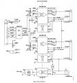
I have been checking the EVAL-ADUM4146 evaluation board for the ADUM4146 gate driver.
In this board, they are using a (2W, +15/-3, +93/-185mA) isolated DC-DC converter module which is the R12P21503D. And in the gate driver datasheet, it says:
What I didn't understand is how come the R12P21503D can deliver that 4.61A peak current and sink the 9A current (pic1).
I know the time is very short probably in the nanoseconds but still?
Can someone explain this to me, please?
Also,
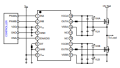
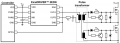
1. what's the difference between using DC-DC modules (pic1) and Isolated SMPS with a transformer (pic2) to create voltage rails for the gate driving circuitry, and just using a non-isolated supply while using pulse transformers instead (pic3)?
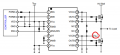
2. what are the pros and cons of using 2 separate biases for the high and low side of a half-bridge and using a single isolated bias (pic4)?
Thank you.
Regard,
I have been checking the EVAL-ADUM4146 evaluation board for the ADUM4146 gate driver.
In this board, they are using a (2W, +15/-3, +93/-185mA) isolated DC-DC converter module which is the R12P21503D. And in the gate driver datasheet, it says:
- 11 A short-circuit source current (0 Ω gate resistance)
- 9 A short-circuit sink current (0 Ω gate resistance)
- 4.61 A peak current (2 Ω gate resistance)
What I didn't understand is how come the R12P21503D can deliver that 4.61A peak current and sink the 9A current (pic1).
I know the time is very short probably in the nanoseconds but still?
Can someone explain this to me, please?
Also,
1. what's the difference between using DC-DC modules (pic1) and Isolated SMPS with a transformer (pic2) to create voltage rails for the gate driving circuitry, and just using a non-isolated supply while using pulse transformers instead (pic3)?
2. what are the pros and cons of using 2 separate biases for the high and low side of a half-bridge and using a single isolated bias (pic4)?
Thank you.
Regard,
Attachments
-
 96.1 KB Views: 9
 -
 20.7 KB Views: 7
 -
 33.3 KB Views: 4
 -
 37.7 KB Views: 5


