hi daveos,
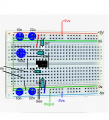
Check this layout option for accuracy, then assemble your bread and post a photoshot of the board before you power up.
E View attachment 290609
hi,
The two Vo wires.
One is the actual Voltage output from the OPA and the other is the 0V ground reference point.
Consider if you used a volt meter to measure the Vout, the +V lead of the meter would go to Vo from the OPA pin#7 and the other meter lead to 0V common/ground.
You must always have a ground 0V connection from the OPA circuit to the 0V of the ADC circuit.
E
Ref: your layout, the bottom 22uF is the wrong way around, Neg should go to the -5V rail.
The 220 resistor on pins #6 & #7 should be 120k.
The 4k7 should be 2k7.
Look at the post #38 circuit, which is a version posted by Alec.
hi,
The two Vo wires.
One is the actual Voltage output from the OPA and the other is the 0V ground reference point.
Consider if you used a volt meter to measure the Vout, the +V lead of the meter would go to Vo from the OPA pin#7 and the other meter lead to 0V common/ground.
You must always have a ground 0V connection from the OPA circuit to the 0V of the ADC circuit.
E
Ref: your layout, the bottom 22uF is the wrong way around, Neg should go to the -5V rail.
The 220 resistor on pins #6 & #7 should be 120k.
The 4k7 should be 2k7.
Look at the post #38 circuit, which is a version posted by Alec.
Thanks again. I appreciate your time and effort in figuring this out. I used different resistors because that's what I had. The gain was about 22 with that configuration. I'll try it out after swapping the polarization on the bottom 22uf resistor.
Well, it does seem to be working. Maybe in a way that is a little too sensitive in the lower frequencies than I had hoped for. Whereas before I'd pick up a fairly wide bandwidth from 10-50hz, it seems now that the resistance on the geophone has really pushed it way below 1hz. Looking at the graph, only the lowest frequencies are seeming to register. Going to let it run for a while and see how sensitive it is to distant earthquakes that tend to register in the 0.1 to 5hz range.
Ideally it should, as theoretically the right-hand op-amp (U1) output can swing above and below ground. In practice the op-amp input offset may keep the output always with the same polarity, or the output swing may be insufficient to de-polarise the cap.
Hi,
That's encouraging news, post images of your signal outputs, if available.
Also note the R6, 210k resistor, I have added that so the signal swings around zero volts.
E @Alec_t
So it appears to have lost most sensitivity above 1hz which might be a bit of overkill for what I was after. I'd have to wait for some low frequency earthquake signals to confirm but I can say that I'm not picking up nearby vehicles or footsteps from the house which I was getting before. I can intuitively tell the circuit is "loading" up the geophone inertial mass when it's hooked up as before I could move it with little effort and hear it moving and now it feels very "stiff". This makes sense for very low frequency signals.
Is there a way to get the signal output to peak around 1hz instead of 1mHz so that the ideal peak response is closer to 1hz but spreads into 10hz?
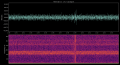
Here is what I'm seeing now. No signals I can make sense of, guessing some EM interference ~20-30hz and the vertical stripe was me downloading data from the Pi.
I ended up dropping that capacitor to 0.22uF for now and the geophone is picking up more local higher frequency signals again. I think it will just be a matter of tweaking it a bit and finding the sweet spot. Need to wait for a larger distant earthquake to verify I'm catching the low end of things.
Thanks. I was afraid of that. For some reason when I set that resistor above 10K I get no voltage output from background signals like cars going by or footsteps. I have to tap near the geophone to register any voltage at all. No idea why.
This configuration seems to be working okay for some reason. Not 100% sure how well it's picking up < 5hz signals, but it seems to be.
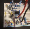
I've attached an mseed file with a 0-5hz quake in it. I can probably convert it to a .wav file if that is helpful. It's hard to get a good pic of the circuit but I've added one.

 Facebook
 Google
 GitHub
 Linkedin