How to extend intercom door unlock time

Thread Starter

mullingover

Joined Nov 25, 2025
24
Hello community. First post here from someone without much electronics knowledge, yet capable of following instructions.

My problem: I have this intercom door/unlock product already installed at my wife’s medical practice. https://www.vimar.com/irj/go/km/doc..._K42910_K42911_K42930_K42931_M1687.109311.pdf

But the time the doorlock is in a state of unlock is only about 1 second and cannot be changed (<ridiculous, but a pricey product that I do not want to change now!). The problem is patients need more time to push open the door. And my wife cannot be leaving patients mid-consultancy to go and open the door, which is currently the issue she has for those not quick enough to react.

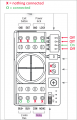
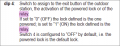
What is needed is to be able to extend the doorlock opening time to about 3 seconds (or better still, be able to choose!). Is it the software/hardware inside the product that determines how long the door remains unlocked for? Or is it the bus distributor that determines how long the ‘unlock pulse’ is for (this is the exact bus distributor (https://www.amazon.fr/VIMAR-42920-D-Distributeur-utiliser-séparer/dp/B0CVN75BGF))?

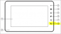
I attach the current wiring. I imagine I might need some extra sort of relay in addition to what already exists? Or perhaps a special but compatible alternative bus distributor? Just to add, all cable distances well within range so isn't a question of lost voltage. Thanks everyone!door wiring.PNG
 

meth

Joined May 21, 2016
298
There are timer relays which require only impulse as input and they would keep the output active for x time - this time is usually set by potentiometer on the relay.
I mean you can make some kind of PCB and make vibrator circuit but this is off-the-shelf tidy solution, the delay function is very precise and the relays come in DIN-mount enclosure. They usually cost around 40 Euros.
The wiring might be a little tricky because the signal that activated the door now has to go on the coil, and you will need a Power Supply signal on the switch side of the relay that you would forward to the door. So except the existing wiring, you will have to take a Power Supply wire for the door.

It is important though to know the voltage of the signal that opens the door, so you buy a relay with the same voltage on the coil.
 

MrChips

Joined Oct 2, 2009
34,626
Bonjour. No wonder with a multilingual instruction manual like that. Something got lost in the translation? I could not find the instructions meth posted. It is in another manual for Vimar 42920.

VIMAR 42920 english.jpg


VIMAR 42920 french.jpg
 

Thread Starter

mullingover

Joined Nov 25, 2025
24
Thanks for the replies. My domestic boss didn't think she saw the extended timer for the relay in the instructions. But we followed the instructions exactly word for word from the online pdf. It changed nothing at all. Then I thought, perhaps unplugging the internal devices completely (for downstairs medical practice and upstairs apartment) would be a general reset. Because this also powers down the outside mounted door buzzers and camera. This being no different at all to the numerous times the devices were unplugged and plugged back in during renovations over the past several months. However, plugging back in ended up with ZERO feed to/from the outside mounted buzzers and camera device. The internal devices power on, can go through menu settings, etc, but there's just no link to the outside. Again, nothing alerted whatsoever with wiring, simply unplugging and plugging back in. I'll search for my multimeter tomorrow to see if any power reaches the BUS distributor or not. Pretty rubbish device, unusable even when "working", especially given the nature of wife's work. I hope to get a refund, unless it miraculously comes on complete with relay time extended.
 

Thread Starter

mullingover

Joined Nov 25, 2025
24
Update: got it "working" again messing around with settings on the internal LCD intercom that are mentioned no where at all in the instructions. (https://www.vimar.com/irj/go/km/doc..._K42910_K42911_K42930_K42931_M1687.109311.pdf)


Long story short, changing the activation time does nothing to the frontdoor (#7). It only affects the door/gate (controlled by button #8, but I have no other door/gate).
1764253041410.png
1764253052346.png


This is silly. So I need the frontdoor controlled by the #8 button, it seems. Page 32 displays the inside of the outdoor station. It is configured as below (as per instructions and as it came out the box):
1764253133017.png

There is this passage (page 34) talking about dip switch #4. I tried that, but changed nothing. Instructions are as clear as mud...
1764253150368.png

Page 49 also talks about the relay, but this seems more for an actual exit gate/"push button to exit" set up and not what I need. But can it be configured to become the frontdoor lock with some trickery?

The manufacturer requests creating an account just to contact them. Hoping for more intelligent help here :)
 

Attachments

xox

Joined Sep 8, 2017
936
I think I've figured out a way to do this with a cheap quad opamp (LM324), a handful of resistors and a couple of capacitors. My design is a somewhat amateur, but perhaps one of our more experienced members could look it over and help work out any kinks it may have. Is this something you might be interested in experimenting with?
 

Thread Starter

mullingover

Joined Nov 25, 2025
24
Which station were you trying to set the delay on?
Hi Sghioto. Appreciate your help. The delay was set using the Master internal station 'A1'. Also tried it on the apartment station 'A2'. In addition to setting the same delay with the door buzzer/camera case open, all set with the same delay time. None of the 3 methods worked in all combinations. The delay is apparently only possible to set on the non-existent gate. Unless all I need to do is rewire to trick it (so the delay for a gate is put on the door lock instead. Then for the internal stations, the 'gate' button is pressed instead of the 'door' button.)? Current set up....
1764319255492.png

Could I rewire it to trick it? So the door lock itself is in effect the 'relay'? I don't want to short anything, so is there any safe option from the below? Which one, if so? What tests could I do with a multimeter? (FYI: there is no exit button and never will be)

OPTION A:
1764317699695.png

OPTION B:
1764320944447.png

OPTION C (seems most logical, if power from 'COM' lasts the seconds needed and has same voltage as 'LOCK'?):
1764321040702.png
Or some other combinations, like I stealing needed power by using 'EXIT' somehow (I presume 'EXIT' is always live and just waiting for a circuit)?
 

Thread Starter

mullingover

Joined Nov 25, 2025
24
I think I've figured out a way to do this with a cheap quad opamp (LM324), a handful of resistors and a couple of capacitors. My design is a somewhat amateur, but perhaps one of our more experienced members could look it over and help work out any kinks it may have. Is this something you might be interested in experimenting with?
Thanks XOX. I first want to check if I can simply reroute some wires (see post I just made). But failing this, I'll certainly read up on your suggestion.
 

sghioto

Joined Dec 31, 2017
8,633
Or some other combinations,
If you can program the unit to delay the relay for the gate I would try this configuration but need a Voltage reading first to verify.
Read the voltage on the COM terminal.
1) Is there +12V all the time?
2) Only when activated and for how long?
3) No voltage at all any time?


1764345818549.png
 
Last edited:

Ya’akov

Joined Jan 27, 2019
10,226
Welcome to AAC.

I would concur with @sghioto. A cheap and cheerful time delay relay board is the easiest and most certain solution.

The ACS's 1-second pulse activates the relay, then the relay provides power to the door lock for the amount of time you configure.

These modules are very inexpensive and generally reliable. However I recommend buying two. This will protect you from failure by having a spare on hand in case the particular module is no longer available. The main advantage being drop-in replacement which will save you time and stress should it be needed.
 

Thread Starter

mullingover

Joined Nov 25, 2025
24
If you can program the unit to delay the relay for the gate I would try this configuration but need a Voltage reading first to verify.
Read the voltage on the COM terminal.
1) Is there +12V all the time?
2) Only when activated and for how long?
3) No voltage at all any time?


View attachment 359627
Hi sghioto,

As always, thanks for your time. It was very hard to get any stable readings, wildly jumping. I don't know if this is part of the design, to first inject higher voltage to flip a lock and then lower voltage to hold it open? Multimeter very stable testing on 12volt car battery, so I think the meter works. Please see below:

GND to LOCK = brief jump around 13volts but drops and bounces around 3 or 4 volts then back to zero in the 1 second that can't be altered.
GND to NO/NC = brief jump around maybe 6 or 7 volts (as much as my eyes could record it) but drops and bounces around 1 or 2 volts then back to zero (but does seem to last the set relay delay).
COM to NO/NC = brief jump around maybe 18 volts (as much as my eyes could record it) but drops and bounces around 1 or 2 volts then back to zero (but does seem to last the set relay delay).

Perhaps not the test results expected. Is there any risk diverting the lock direct to COM and NO/NC, causing something to short? This seemed to give a reading more like it was tackling something. Could this be dangerous, putting too much electricity onto the lock mechanism someone might touch? I guess I could measure that too.

Thanks again!
 

sghioto

Joined Dec 31, 2017
8,633
Those fluctuating readings generally indicate a data signal or PMW (pulse modulated waveform)
How much delay was on the reading from GND to NO/NC?
Also measure from GND to COM then again when activated please.
Do you have a 12 volt lamp or LED to use for testing?
 
Last edited:

xox

Joined Sep 8, 2017
936
Just out of curiosity, I wonder if something like this might do? I used a similar circuit for my bike horn and it worked just fine.

unlock-delay.png

Of course that's assuming that the door unlock signal can be safely operated at 12V for the entire duration of the delay. The larger the value for resistor Rt, the longer the delay, but in any case you'd probably need to find the best value experimentally (or just use a potentiometer). I chose a divider voltage of ~1.5V since you said that the signal can be as low as 3V (and you don't need the momentary switch, I just put it there for simulation purposes). An opamp can be used in place of an actual comparator. For my bike circuit, I went with an LM358 dual DIP with the unused opamp inputs/outputs tied to ground.
 

Thread Starter

mullingover

Joined Nov 25, 2025
24
Those fluctuating readings generally indicate a data signal or PMW (pulse modulated waveform)
How much delay was on the reading from GND to NO/NC?
Also measure from GND to COM then again when activated please.
Do you have a 12 volt lamp or LED to use for testing?
Sorry for lacking details. Please see replies, but apart from these details the outside device was heard clicking on and off based on timer delay. No reading ever read a completely stable zero (closest to zero hovering close to zero)....

How much delay was on the reading from GND to NO/NC?
>Higher voltage at beginning, fluctuating and phasing out it seemed. Duration of all the up and downs based on what the delay was (set to 10 seconds).

Also measure from GND to COM then again when activated please.
>seemed to be little or nothing at all between these points. Just hovering close to zero.

Do you have a 12 volt lamp or LED to use for testing?
>no, but I have been known to wire up a car lightbulb to do this. Shall I try? What would I expect?
 
Top