Extend Frequency Range of 4.5hz Geophone

Alec_t

Joined Sep 17, 2013
15,146
The circuit I posted was just a proof of concept simulation to try and provide some frequency compensation. A real-world circuit might need a fair bit of tweaking as the internals of the geophone are not fully known. You would almost certainly need an additional amplification stage. C1 should be a non-polarised type (or two polarised back-to-back).
But as Jon pints out, there's very little signal to amplify. Unwanted ambient noise could be a major issue to deal with.
 

Thread Starter

daveos

Joined Mar 19, 2023
39
hi,
If you are attempting to model a geophone in the real world on your project you could add them, but if you have the actual geophone, the answer is you do not need to add the components;
They have been created by Alec to mimic a real geophone. OK.?
E
Thanks. I just wasn't clear where the geophone ended and where the circuit started. I have the geophone, yep.
 

Thread Starter

daveos

Joined Mar 19, 2023
39
I think you're missing the key feature here. If I understand correctly, you want to see data down to 0.1Hz. You're out of gas. There's no signal to amplify at 0.1Hz. The slope of the response below 5.4Hz is 40dB/decade. At 0.1Hz, the response is about 50dB down (assuming the slope continues off the graph) - about 1/300 less response than at 5.4Hz.

View attachment 290236
I'm far from any kind of expert on this, but I was under the impression that is what a force balance circuit did - extended the capabilities of the geophone. This is done in the paper I linked to, and by raspberry shake, which also uses a force balanced bandwidth extended 4.5hz geophone. That is the goal anyway.
 

Thread Starter

daveos

Joined Mar 19, 2023
39
The circuit I posted was just a proof of concept simulation to try and provide some frequency compensation. A real-world circuit might need a fair bit of tweaking as the internals of the geophone are not fully known. You would almost certainly need an additional amplification stage. C1 should be a non-polarised type (or two polarised back-to-back).
But as Jon pints out, there's very little signal to amplify. Unwanted ambient noise could be a major issue to deal with.
Hi Alec,

So there is another amplification stage. The ADC has a built in amplifier that works well and goes up to 16 gain, and is programmable. That is what I was using to amplify what I had and it was working great between about 8 and 60hz. Just trying to push it farther down.

If I'm getting this right, you have built the same circuit that was in the paper I posted, I don't see any differences? All I need to do then to match your circuit is swap out R3 (I had 290K) and R4 (I had 10K) and the 0.1uF cap with a 100uF cap? So If I get this right you're setting the gain (1 + R4/R3) to 23.5? I have a bunch of resistors, but none that are 2700. As long as I hit gain close 23.5 can I use a different combination?

Gracias.
 

ericgibbs

Joined Jan 29, 2010
21,517
Hi Jon,
Read the link in post# 4, showing a method of extending the lower range response.
The author and his team have posted results indicating/claiming this is possible.
E
 

Thread Starter

daveos

Joined Mar 19, 2023
39
Your choice entirely. The gain I used was arbitrary.
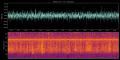
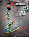
Well, got it wired up. Getting signals fine, doesn't seem to be extending that 0-10hz sensitivity much though unfortunately. I think I wired it up correctly. Vertical stripes are cars driving by my house. Horizontal signal is a fan running.
 

Attachments

joeyd999

Joined Jun 6, 2011
6,390
An LM358 has a 1/f noise corner at about 60Hz. This is simply the wrong part to use in a sub 10Hz application, especially if additional gain is required below 4.5Hz.

Use a good zero-drift amp and very low tempco resistors. This will greatly increase the sensitivity of your geophone.
 

Thread Starter

daveos

Joined Mar 19, 2023
39
Use a good zero-drift amp and very low tempco resistors. This will greatly increase the sensitivity of your geophone.
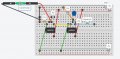
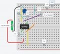
Is this the correct way to wire that circuit up? The orange wires are the resistors.

Do you have an opamp you can recommend? I have a few on hand I ordered. LM324, LM358, LM386, LM393, UA741, NE5532, NE555, PC817, ULN2003, ULN2803?

Thanks
 

Attachments

joeyd999

Joined Jun 6, 2011
6,390
Is this the correct way to wire that circuit up? The orange wires are the resistors.

Do you have an opamp you can recommend? I have a few on hand I ordered. LM324, LM358, LM386, LM393, UA741, NE5532, NE555, PC817, ULN2003, ULN2803?

Thanks
I use LTC2050s. Aside from that, I've no comment as I haven't carefully read this thread.

Others will chime in.
 

ericgibbs

Joined Jan 29, 2010
21,517
Hi daveos,
Which circuit diagram did you use for the post #30 testing.?
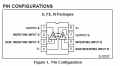
The layout and pinning of the bread board circuit post #32, looks completely wrong.???
E
 

Thread Starter

daveos

Joined Mar 19, 2023
39
Hi daveos,
Which circuit diagram did you use for the post #30 testing.?
The layout and pinning of the bread board circuit post #32, looks completely wrong.???
E
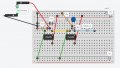
That was supposed to be the layout from #15. Apparently I did not get it right. I see the opamps are backwards in the diagram. Updated here.
 

Attachments

ericgibbs

Joined Jan 29, 2010
21,517
hi,
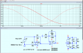
This diagram shows the pin numbers, also the essential decoupling capacitors for the project/

The LM358 is a Dual OPA.


@daveos Redo the bread board layout using this circuit and pin numbers.

E
EG57_ 715.pngEG57_ 713.png
 
Last edited:

Thread Starter

daveos

Joined Mar 19, 2023
39

Attachments

Top