Facebook
 Google
 GitHub
 Linkedin

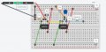
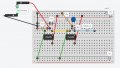
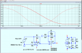
The circuit I posted was just a proof of concept simulation to try and provide some frequency compensation. A real-world circuit might need a fair bit of tweaking as the internals of the geophone are not fully known. You would almost certainly need an additional amplification stage. C1 should be a non-polarised type (or two polarised back-to-back).
But as Jon pints out, there's very little signal to amplify. Unwanted ambient noise could be a major issue to deal with.
But as Jon pints out, there's very little signal to amplify. Unwanted ambient noise could be a major issue to deal with.