Extend Frequency Range of 4.5hz Geophone

Thread Starter

daveos

Joined Mar 19, 2023
39
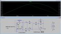
I took the advice above and installed the NE5532, found the LTspice profile for it online. Messing with this configuration now. Seems to be picking up lower frequencies. Stuck working the next few nights but if a > 6.5m earthquake happens somewhere I'll be able to see if it registers. Really just trying out different combinations of C1 and R3 to see how it responds. Making progress. Need to order a few LTC2050s.:)
 

Attachments

ericgibbs

Joined Jan 29, 2010
21,530
Because the TS is trying to extend the lower cut frequency cut off of his geo sensor.
The recording being used was from a 'regular' geo of unspecified performance.
I considered it worthwhile testing the circuit, using the recording into a LTS voltage source and the geo model.

Is there a problem with that?
 

Thread Starter

daveos

Joined Mar 19, 2023
39
Just an update. Took a break from this for a while as things in my life went extremely hectic.

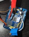
Got around to sticking it together on a circuit board. I think something was wrong with the breadboard I was using.

Anyway, after moving it to the circuit board the V0 was running at about 3.8v. I wasn't sure how to drop this so I tried the configuration shown (I think that is how it ended up) to drop the voltage at V0. This worked, and the voltage dropped to about 0.2v.

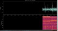
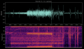
I installed two variable resistors, set at 120k and 2.2k as shown in the diagram. All in all it seems to be working better than it has yet, I'm seeing a lot more signals in the 0-5hz range. I'm not sure if that 3rd 10K resistor is in the right spot to drop the voltage correctly at V0.

Red = +5v. Orange = gnd. Brown = -5v

Capture.JPGFigure_1.pngScreenshot_20230415_165857_Gallery.jpg
 
Last edited:

Alec_t

Joined Sep 17, 2013
15,149
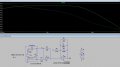
The added 10k (R5) will have reduced the gain for signals below ~1Hz, cancelling the main purpose of my circuit but also reducing 'clutter' which may have been hiding signals in the 1-5Hz range. Since it is in parallel with the 120K pot (R3), varying the pot much above 10k will have little noticeable effect.
The circuit frequency response with the added 10k is now as below:-
1681639414349.png
 

AlexB2

Joined Oct 20, 2024
1
Hi Davos,
I saw your post regarding the efforts to extend the eigen period of the Geophone.
May I kindly ask what ADC part you used and what software was loaded on the PI board? Is the mseed file attached recorded by the PI board?
 

MisterBill2

Joined Jan 23, 2018
27,980
I have actually USED a Kistler servo accellerometer, used to sense vibrations. So I understand the force feedback concept.
But what the TS is really seeking is an increase in low frequency sensitivity, well below the geophone mechanical resonance frequency. For that I suggest starting with a much better amplifier, such as been shown in another thread. That could be an AD623 or an AD8422, or one of the other very low nice, DC response, instrument amplifiers. In fact, the AD website may even have some design examples of geophone amplifiers. The LM358 is a nice experimentor amplifier but there are some available that are vastly better.
 
Last edited:
Top