Extend Frequency Range of 4.5hz Geophone

ericgibbs

Joined Jan 29, 2010
21,531
Hi,
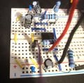
I have checked your circuit layout, it looks OK.
Is the 100uF a polarised cap.?

What DC voltage do you measure on pins #1 and #7 when the 120K is used.?

If you could convert that file to a wav file it would be helpful. To upload ti the Thread add .txt to the name.
eg: sound.wav.txt
E
Tidied up your image.
Screenshot_20230327_003817_Gallery.jpg
 

Thread Starter

daveos

Joined Mar 19, 2023
39
Hi,
I have checked your circuit layout, it looks OK.
Is the 100uF a polarised cap.?

What DC voltage do you measure on pins #1 and #7 when the 120K is used.?

If you could convert that file to a wav file it would be helpful. To upload ti the Thread add .txt to the name.
eg: sound.wav.txt
The 100uF cap is polarized, with the - to the left. I have a non polarized one as well I can use.

I have a 100K resistor, which is close. When I put that in with the 2.2K resistor the voltage at pin 1 is -090 with the multimeter set to 2000m. The voltage at pin 7 is -868 set to 2000m. This was measuring directly onto the pin with ground to the common ground.

Attached the .wav. I'm not sure if the time sampling was preserved.

Thanks
 

Attachments

Thread Starter

daveos

Joined Mar 19, 2023
39
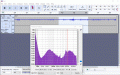
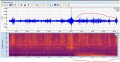
Yeah, that looks right. The quake is off to the right side in the lowest frequencies. Distant large quakes are pretty muted like that.

Cheers
 

Attachments

Thread Starter

daveos

Joined Mar 19, 2023
39
Hi,
Please measure the DC voltage on the Geo input pin to pin#2, your test wav has a +0.6Vdc offset.???

E
Sorry I didn't clarify. That test.wav is not from the geophone we are working on. It is a different system. Just meant to be an example of a low frequency earthquake.
 

ericgibbs

Joined Jan 29, 2010
21,531
hi,
OK.
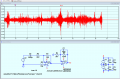
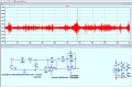
This is what the original sim circuit shows for the wav file, the 1000uF removes the DC offset.
I will now try with Alec's Geo model.
E
EG57_ 728.png
 

ericgibbs

Joined Jan 29, 2010
21,531
Hi,
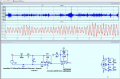
This is using Alec's model for the Geo, not quite sure to make of the resultant output, seems time shifted about -0.8secs.
Also the amplitude is down, the top plot is the input 'wav'

E

EG57_ 729.png
 

Thread Starter

daveos

Joined Mar 19, 2023
39
Hi,
This is using Alec's model for the Geo, not quite sure to make of the resultant output, seems time shifted about -0.8secs.
Also the amplitude is down, the top plot is the input 'wav'

E
Yeah, I think the time sampling isn't going to allow this to model right. The original wave data is almost 10 minutes long, it's compressed into 8 seconds.
 

Thread Starter

daveos

Joined Mar 19, 2023
39
I'm still figuring out how to convert these files to .wav. This one should preserve the time sampling as well. ~10minutes long.

Cheers
 

Attachments

ericgibbs

Joined Jan 29, 2010
21,531
hi,
This is the 10min wav file.
E

BTW: I have to get back onto my own projects for a few hours, so maybe a little delay in replying.:)


@daveos Note: the signal amplitude is too high from the test wav signal, it is saturating the amplifiers, needs to be attenuated before the input.

EG57_ 730.png
 

Attachments

Last edited:

Thread Starter

daveos

Joined Mar 19, 2023
39
hi,
This is the 10min wav file.
E

BTW: I have to get back onto my own projects for a few hours, so maybe a little delay in replying.:)
That looks better. We'd have to filter it with a butterworth filter at about 0.1-5hz to see if the earthquake signal comes through. I'll see if I can revert the wav back to data I can plot on a spectogram. It does look like it's there.

I still don't get why I can't put the 120k resistor in, strange.

I'm off to bed. Thanks again for the help.
 

AnalogKid

Joined Aug 1, 2013
12,238
Do you have an opamp you can recommend? I have a few on hand I ordered. LM324, LM358, LM386, LM393, UA741, NE5532, NE555, PC817, ULN2003, ULN2803?
Note that four of those are not opamps.

Of the ones that are, only the NE5532 is a true low-noise, low distortion opamp.

Does this look right using both sides of one opamp instead of two?
The circuit needs two power supply decoupling capacitors. These go from the power pins to GND. Mount them as close to the chip as possible, with short leads.

ak
 

AnalogKid

Joined Aug 1, 2013
12,238
Not great, but better than anything else in that list. And, while the 1/f corner freq is relatively high, the magnitude of the noise is still way better than those other guys.

ak
 

Thread Starter

daveos

Joined Mar 19, 2023
39
Something strange is happening when I swap components out for testing. I swapped out the LM358 for the NE5532 and the signal was blown out. I swapped them back and the signal was still blown out when it was working fine before. Powered circuit down before swapping.

Are the capacitors holding a charge between changes? Is there a way to discharge them?
 

ericgibbs

Joined Jan 29, 2010
21,531
Hi daveos,
The 100uF should discharge through the parallel 120k, the other decoupling capacitors should not cause the OPA failures.
I assume you are switching Off the power source before OPA swapping.?

When you say the signal was blown out, exactly what do you mean?
E
BTW: may I ask which part of the World are working from, for the seismic sensor project.
 

Thread Starter

daveos

Joined Mar 19, 2023
39
Hi daveos,
The 100uF should discharge through the parallel 120k, the other decoupling capacitors should not cause the OPA failures.
I assume you are switching Off the power source before OPA swapping.?

When you say the signal was blown out, exactly what do you mean?
E
BTW: may I ask which part of the World are working from, for the seismic sensor project.
I got it figured out. I had two pieces of software running that were setting the ADC gain and I had forgot to disable one while I was tweaking the other, so it was setting conflicting gains.

I'm in the southwest USA.
 

ericgibbs

Joined Jan 29, 2010
21,531
Hi daveos,
Phew!.;)
Thanks for the positive feedback.
At what stage are you at now, with the project.?
E

BTW: A complete circuit of the project would help us, help you.
 
Top