Facebook
 Google
 GitHub
 Linkedin
MisterBill2
- Joined Jan 23, 2018
- 27,841
Normal electric motors do not operate in a constant power mode. So if the voltage is reduced the current will drop. And so will the torque and the speed.
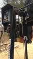
For a great deal more capability you can have the gearbox turn a lead-screw. That will give a lot more force, do a linear move, and avoid any creeping while sawing.
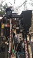
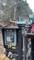
AND, now I see it is a lumber mill, and not a metal working milling machine. I was a bit confused.
For a great deal more capability you can have the gearbox turn a lead-screw. That will give a lot more force, do a linear move, and avoid any creeping while sawing.
AND, now I see it is a lumber mill, and not a metal working milling machine. I was a bit confused.