Circuit Design for Toddler’s LED “busy board”

Thread Starter

pi_pilot

Joined Feb 16, 2022
13
Hi there,

I am new to this form and new to electronics in general. Apart from occasionally wiring a plug I haven’t really dealt with electronics since leaving school 15 years ago.

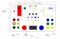
I am planning on making a “busy board” for my son. It’s basically a 200 x 120 x 50 mm plastic box with holes drilled in it for various on / off switches and LEDs. The idea is he can safely toggle and press the various switches and the LEDs will come on / off as he does so. I have attached a sketch of what it will look like.

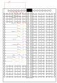
I’m trying to keep the circuitry very simple – basically it will be a number of switches, resistors and LEDs connected in parallel to a 9V battery. I have been reading up on LEDs and understand that you need to protect them with a resistor to stop them from burning out from a higher voltage. I also understand that the required resistance can be calculated from Ohm’s law. The problem I have is that the number of LEDs (and hence the current drawn) will vary depending on how many switches my son has “on” at that point. How do I go about calculating a resistance required for each LED which will stop it being damaged when all other LEDs are “off” but will not reduce the light output too much when the majority of other LEDs are switched on?

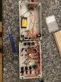
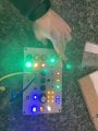
I have attached a very rudimentary circuit diagram (apologies if this isn’t clear but I haven’t drawn one before). I have a breadboard that I’m practicing on so for the “busy board” I’m planning on just soldering the LEDs and battery to a matrix board to keep it simple.

I would greatly appreciate any other advice you could give to help me finish this project. I have a small selection of other electronic components at home such as capacitors, transistors, relays and variable resistors if utilising any of these would help.

Many thanks in advance.
 

Attachments

AnalogKid

Joined Aug 1, 2013
12,090
I don't see a connection between +0 V and the main distribution bus.

Separate from that, you are off to a good start. With one resistor per LED (the right way), things are very easy to calculate. An LED, like a simple diode, has a forward voltage Vf. This is the voltage drop across the diode when it is "on", conducting current in the forward direction. For generic small LEDs, reds come in a little below 2 V and greens come in a little above. Since you're not designing an instrument panel for the space shuttle, you can go with 2.0 V for all reds, yellows, and greens. Blue and white are different.

Starting with a 9 V battery, the simple circuit math is in fact Ohm's Law, once you see that from the resistor's point of view, E isn't 9 V, it's 7 V: A constant 9 V from the battery, minus a constant 2 V across the LED. To conserve battery life, let's run the LEDs at a current of 10 mA instead of the more common 15 or 20 mA. Note, 10 mA = 0.01 A.

E = I x R

R = E / I

R = 7 / 0.01

R = 700 ohms

That is not a standard 5% tolerance value, so you can drop that to 680 or increase it to 750.

Your schematic shows multiple parallel LED paths. Within reason, you can turn any of them on and off and the current through each will be the same. At some point, the total current draw will be too much for the battery, and turning on additional LEDs will decrease the brightness of all of them. But until you reach that point, they should be independent of each other.

Where are you located?

ak
 
Last edited:

Thread Starter

pi_pilot

Joined Feb 16, 2022
13
Many thanks for the clear and quick response.
I will give that a go tonight on my breadboard to see how many LEDs + resistors I can run in parallel from a 9V battery.
I'm located in the UK.
 

crutschow

Joined Mar 14, 2008
38,423
To maximize battery life, use high brightness type LEDs and used the largest resistance in series that will give the desired brightness (that may require only a few mA per LED).
Also some color LEDs will appear brighter than other colors so you may want to select different resistors for different colors to match brightness.
 

Tonyr1084

Joined Sep 24, 2015
9,744
Welcome to AAC.

Basic circuit:
1645025690152.png
Same circuit but showing common grounds with push button switch:
1645025741332.png
Your child's light board:
1645025775677.png
You have the concept down. Just remember that the more LED's that are simultaneously lit the more current being drawn from the battery. In this scenario you multiply the individual LED current times the number of circuits you want lit at any given moment. Unless you use toggle switches I don't see how a child can manage to get a few LED's lit at any one time.
 

Tonyr1084

Joined Sep 24, 2015
9,744
To maximize battery life, use high brightness type LEDs and used the largest resistance in series that will give the desired brightness (that may require only a few mA per LED).
Also some color LEDs will appear brighter than other colors so you may want to select different resistors for different colors to match brightness.
Yes. In fact, "Super Bright" LED's can be quite bright. The amount of light can be harmful to the human eye. Better current for such bright LED's would be down at or below 5mA (0.005A). And different colors WILL appear different brightnesses. Remember to keep them low so they don't harm the child's eyes.

The wavelength of standard LED's is not in itself harmful to the human eye, not like infra-red laser pointers can be. So you don't need to be afraid of the standard LED. However, it's the intensity that can be harmful, so keep them turned down to where they can be seen easily in a normally lit room. Perhaps not bright enough to be seen in full direct sunlight. That way in a darkened room the light won't appear too bright.
 

Ya’akov

Joined Jan 27, 2019
10,226
Somewhat tangential but the PP3 (9 volt) battery is a very expensive and not very long-lived way to power anything. I would encourage you to consider a different, preferably rechargeable source.

Something like this, with a pair of AA NiMH rechargeable cells would last longer and be extremely more cost effective. Of course you would have to recalculate your resistors for the 2.8V, or if there were white LEDs get the 3S version and use 3 cells for 4.2V. There are other more complicated and possibly nicer solutions for future projects if you are interested.

1645026200220.png
 

Tonyr1084

Joined Sep 24, 2015
9,744
I believe I saw in your diagram some potentiometers. You still want to use a fixed resistance to limit the amount of brightness that can be achieved when the pot is turned all the way up (zero resistance). That protects two things: Eyes; and you don't blow out the LED from too much current.
 

Thread Starter

pi_pilot

Joined Feb 16, 2022
13
Hi all, thanks for your responses!
Unfortunately I didn’t see Tonyr1084’s response before I went ahead and built the thing and you’re right - it’s far too bright! It has actually hurt my eyes testing it so can’t give it to my kid. I’ll have to put in some higher resistors. My wiring / soldering is quite messy so not going to be an easy job :(
 

Attachments

Thread Starter

pi_pilot

Joined Feb 16, 2022
13
The other thing I’m struggling with is that in the middle I wanted to put a RGB LED with three potentiometers so he could change the colour of the light. I’ve blown two RGB LEDs so far because I’ve got the resistance too low but when I put a higher one in I can only rotate the potentiometer a few degrees before the resistance is so high it switches that colour off completely… any ideas how I could fix this?
 

Thread Starter

pi_pilot

Joined Feb 16, 2022
13
Somewhat tangential but the PP3 (9 volt) battery is a very expensive and not very long-lived way to power anything. I would encourage you to consider a different, preferably rechargeable source.

Something like this, with a pair of AA NiMH rechargeable cells would last longer and be extremely more cost effective. Of course you would have to recalculate your resistors for the 2.8V, or if there were white LEDs get the 3S version and use 3 cells for 4.2V. There are other more complicated and possibly nicer solutions for future projects if you are interested.

Thanks for this - perhaps cutting out my 9v battery and soldering in one of these would be an easy way to fix my problem of the LEDs being far too bright…
 

AnalogKid

Joined Aug 1, 2013
12,090
The other thing I’m struggling with is that in the middle I wanted to put a RGB LED with three potentiometers so he could change the colour of the light. I’ve blown two RGB LEDs so far because I’ve got the resistance too low but when I put a higher one in I can only rotate the potentiometer a few degrees before the resistance is so high it switches that colour off completely… any ideas how I could fix this?
Not trying to be snarky or anything, but - change the value of the pot.

Better yet, post a schematic with reference designators and values, and let us change the value of the pot.

For improved adjustability, what you want is a fixed resistor in series with the pot. The resistor sets the max current/brightness (when the pot's resistance is 0), and the max value of the pot sets the minimum current/brightness. For example, with a 9 V batter, a 1 K fixed resistor sets the max LED current at around 7 mA (need to know the type of LED for a real value). A 10 K pot lowers this to a minimum of 0.6 mA. Both of these are safe values for a typical LED.

LED part number / vendor page?

Resistance value = (voltage across the resistor) / (desired LED current)

The voltage across the resistor combo is the battery voltage minus the LED forward voltage (Vf). For a tri-color LED, each color will have its own Vf.

As a starting point for the desired LED current, I use the datasheet "typical" value (often in the notes as the test condition for things such as the brightness measurements) as the max, and 10% of that as the min.

ak
 
Last edited:

Thread Starter

pi_pilot

Joined Feb 16, 2022
13
Not trying to be snarky or anything, but - change the value of the pot.

Better yet, post a schematic with reference designators and values, and let us change the value of the pot.

ak
I’m not at my computer at the moment so can’t post a schematic but I have the common anode of a RGB LED attached to 9V, then each individual cathode attached to a 1k ohm resistor then an individual 200K Linear 16mm Splined Potentiometer. I’m guessing those “pots” are far too big and I need a much smaller ones? Seems obvious now you suggest it.
 

Thread Starter

pi_pilot

Joined Feb 16, 2022
13
Not trying to be snarky or anything, but - change the value of the pot.

Better yet, post a schematic with reference designators and values, and let us change the value of the pot.

For improved adjustability, what you want is a fixed resistor in series with the pot. The resistor sets the max current/brightness (when the pot's resistance is 0), and the max value of the pot sets the minimum current/brightness. For example, with a 9 V batter, a 1 K fixed resistor sets the max LED current at around 7 mA (need to know the type of LED for a real value). A 10 K pot lowers this to a minimum of 0.6 mA. Both of these are safe values for a typical LED.

LED part number / vendor page?

Resistance value = (voltage across the resistor) / (desired LED current)

The voltage across the resistor combo is the battery voltage minus the LED forward voltage (Vf). For a tri-color LED, each color will have its own Vf.

As a starting point for the desired LED current, I use the datasheet "typical" value (often in the notes as the test condition for things such as the brightness measurements) as the max, and 10% of that as the min.

ak
LED data:
Switch Electronics
RGB
40-100mA
Red 1.9V, Green 3.0V, Blue 3.0V
-40°C to +85°C
Red 5000mcd, Green 12000mcd, Blue 6000mcd
30°
5mm
Red 625nm, Green 520nm, Blue 470nm
 

Audioguru again

Joined Oct 21, 2019
6,826
I see a solderless breadboard that will disconnect many parts and possibly cause the battery to make a fire if the project is dropped on the floor. Instead solder all the parts and wires together.

The LEDs are too bright and will blind your son and kill the little 9V battery in 4 hours if all 14 LEDs are turned on. The battery is so weak that you will see it cause dimming when it is new.

When the speaker is connected to the battery it will make one POP and kill the battery in a couple of minutes. If you use a piezo beeper then it will deafen your son.

With a 9V battery, a 2V red LED in series with a 200k pot produces a current of only 35uA which is nothing so the LED will be off.
When a linear pot is used then it is 100k when turned to halfway and the current is still only 70uA which is also nothing.
Maybe a current of 240uA is dim enough then the resistance of the pot will be 25k with a 3.9k resistor in series.
For the brightness to be changed smoothly with a pot it should be logarithmic, not linear.
 

k1ng 1337

Joined Sep 11, 2020
1,038
LED data:
Switch Electronics
RGB
40-100mA
Red 1.9V, Green 3.0V, Blue 3.0V
-40°C to +85°C
Red 5000mcd, Green 12000mcd, Blue 6000mcd
30°
5mm
Red 625nm, Green 520nm, Blue 470nm
You can use this information to determine the series resistor value for maximum brightness (pot set to zero resistance) and then use your 200k pot to determine the minimum brightness (ohm reading on multimeter). Then find a pot value for your minimum brightness based on the resistance set on the 200k pot. You can use ohm's law on paper and/or you can use your 200k pot and a multimeter. Do you know how to do this? As Audioguru has said, a 100 or 200k pot will be far too much resistance to deliver the required current (ohm's law) though experimenting with your 200k pot will give a large resistance range and is useful for finding the forward voltages (and currents) of your LEDs. In any case, an ohm's law calculator app on your phone will come in handy.
 

MrSalts

Joined Apr 2, 2020
2,767
am planning on making a “busy board” for my son.
First, toy manufacturers very carefully design cases for toys with a team of engineers, large budgets, modern manufacturing methods with materials that are carefully tested for strength, impact resistance and extraction of additives by saliva or common cleaning products. Yet, every year there are recalls of toys because parts fall of, become choking hazards, or even a toxic ingestion issue, or fire hazard, or, or, or,... point is, I hope this is not built to keep your son occupied while you work - a sleeping baby makes the same sound as a choking baby - a real choke isn't a cough.

Second, if you do plan on playing with this with the baby, then you'd be much better off playing with the baby and talking to him/her while they look at your face, look at your mouth forming words, your eyes and mouth making expressions.

Third, my 90+ year old mother figured out how to use a computer in her 70s, a iPhone in her 80s and Alexa in her 90s. She was ok with a late start. Your kid will have plenty of time to figure out how electronics gadgets work and catch up with his peers.

Finally, it seems to me that new parents thst want to start new hobbies when their kid needs them most needs a mentor to tell them, "now is not the time. Your baby should fill any free time you have until further notice."
 

Thread Starter

pi_pilot

Joined Feb 16, 2022
13
First, toy manufacturers very carefully design cases for toys with a team of engineers, large budgets, modern manufacturing methods with materials that are carefully tested for strength, impact resistance and extraction of additives by saliva or common cleaning products. Yet, every year there are recalls of toys because parts fall of, become choking hazards, or even a toxic ingestion issue, or fire hazard, or, or, or,... point is, I hope this is not built to keep your son occupied while you work - a sleeping baby makes the same sound as a choking baby - a real choke isn't a cough.

Second, if you do plan on playing with this with the baby, then you'd be much better off playing with the baby and talking to him/her while they look at your face, look at your mouth forming words, your eyes and mouth making expressions.

Third, my 90+ year old mother figured out how to use a computer in her 70s, a iPhone in her 80s and Alexa in her 90s. She was ok with a late start. Your kid will have plenty of time to figure out how electronics gadgets work and catch up with his peers.

Finally, it seems to me that new parents thst want to start new hobbies when their kid needs them most needs a mentor to tell them, "now is not the time. Your baby should fill any free time you have until further notice."
I came here for electronics device but I see this thread has digressed to parental advice. Thanks for this but you clearly don’t know what you’re talking about. I did not say I am giving this to a baby - there’s quite a big difference between a 3.5 year old toddler and a baby.
It’s quite bizarre to suggest I’m neglecting my son because I decided to make him something rather than buying him a toy. I assume your 90+ year old mother had all her toys sourced via modern manufacturing methods?
I think I have all the information I need now and thank the helpful responses however I think this thread has now run its course.
 
Top