Facebook
 Google
 GitHub
 Linkedin
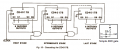
Yes, they lose memory when power is lost.I'll probably be going with shift registers. They're not too expensive, and after searching YouTube for videos I think I have the idea of how to program it. Is their memory volatile?
But they only draw a very small leakage current when static, so you can keep their memory alive with a coin cell for months if not years.