Facebook
 Google
 GitHub
 Linkedin
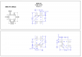
The MB6S is a useful little 800mA bridge rectifier in a 4-pin surface mount package. I use quite a few of them, but I was beginning to wonder why my colleague has a hard time getting them on the pcb the right way round, especially as if I switch in the power without noticing it is wrong, it blows a track off the board.
Then I looked at the datasheet:

Vishay: Pins 1 and 2 are the AC input pins.

OnSemi: Pins 1 and 2 are the output pins.
Then I looked at the datasheet:
Vishay: Pins 1 and 2 are the AC input pins.
OnSemi: Pins 1 and 2 are the output pins.