Facebook
 Google
 GitHub
 Linkedin
I have problem with output of Full wave bridge rectifier.
Source: 220V RMS, 50 Hz
Diode: 1N4007
Resistor: 680 ohm (load)
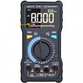
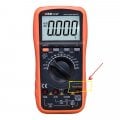
Multimeters: Hioki DT4256 and Zoyi (True RMS)
Is the RMS value the same after you pass it through a full wave bridge rectifer?
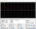
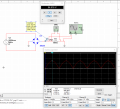
According to the figure below, I connected a resistor to 220V RMS via a diode bridge. I set the multimeter to AC mode and measured the voltage across resistor while applying alternating current as the voltage source.
results:
AC voltage across resistor: 94.9v , Vmax : 308v , Irms: 321 mA
Problem: Why is the voltage across the resistor in AC mode is 94 volts while according to the formula Vrms= Vmax/ √ 2 = 308 / √2 = 218v , but multimeter show 94.9v. On the other hand, The current flowing through the resistor (Irms) is 321mA, Vrms= R * Irms = 680 * 0.321 = 218v , but multimeter show 94.9v
Source: 220V RMS, 50 Hz
Diode: 1N4007
Resistor: 680 ohm (load)
Multimeters: Hioki DT4256 and Zoyi (True RMS)
Is the RMS value the same after you pass it through a full wave bridge rectifer?
According to the figure below, I connected a resistor to 220V RMS via a diode bridge. I set the multimeter to AC mode and measured the voltage across resistor while applying alternating current as the voltage source.
results:
AC voltage across resistor: 94.9v , Vmax : 308v , Irms: 321 mA
Problem: Why is the voltage across the resistor in AC mode is 94 volts while according to the formula Vrms= Vmax/ √ 2 = 308 / √2 = 218v , but multimeter show 94.9v. On the other hand, The current flowing through the resistor (Irms) is 321mA, Vrms= R * Irms = 680 * 0.321 = 218v , but multimeter show 94.9v
Attachments
-
 18 KB Views: 37
 -
 49.3 KB Views: 39